7PG2113/4/5/6 Commissioning & Maintenance
©2012 Siemens Protection Devices Limited
Chapter 6 Page 16 of 77
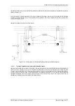
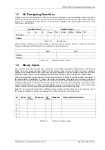
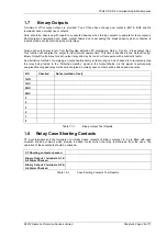
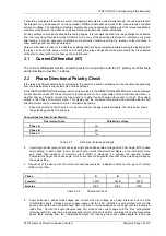
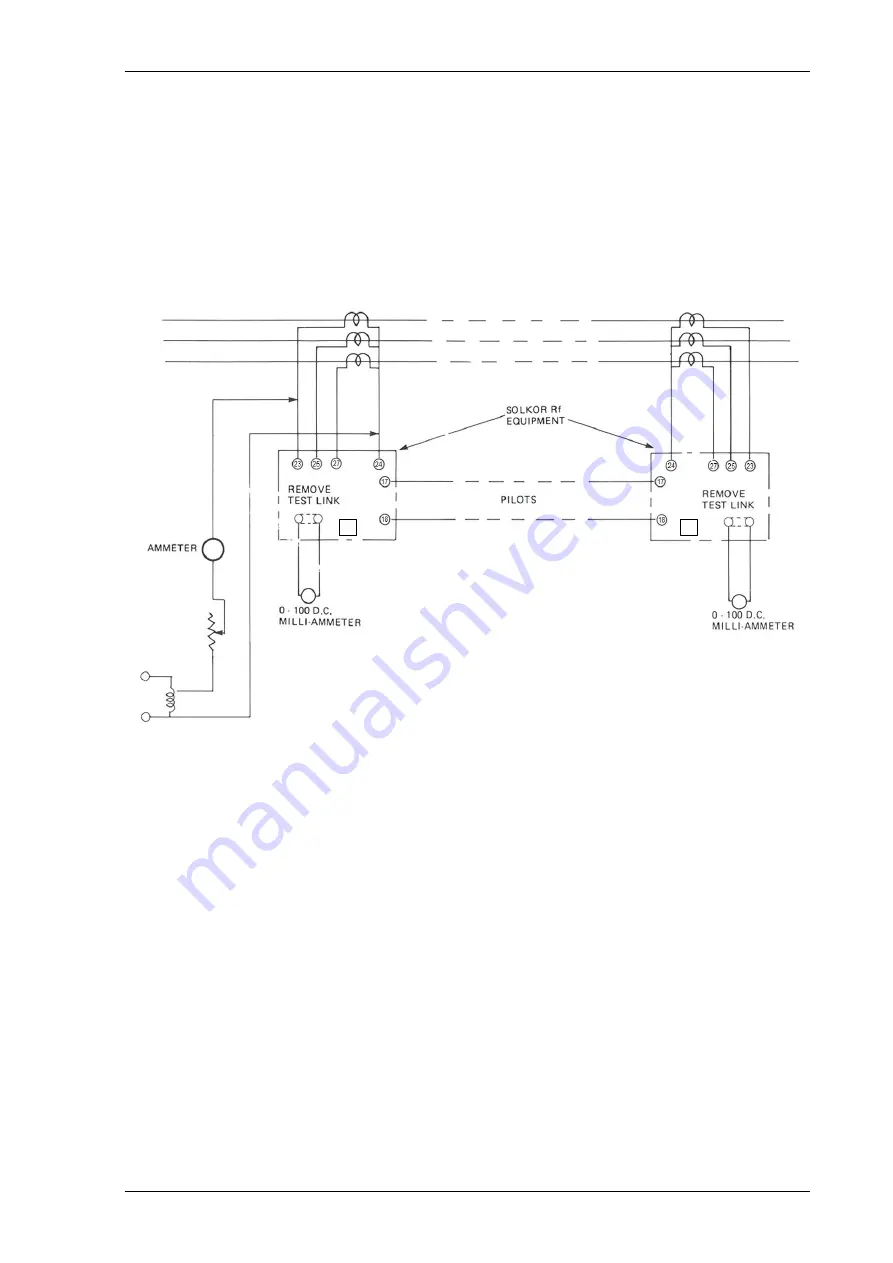
Repeat the tests for the other earth fault conditions and also for the phase fault conditions. Tabulate the results as
shown in
Table 1.4-1
.
If it is convenient to permit operation of the circuit breaker at this stage, repeat one of the tests with the trip links
inserted. Increase the test current to the setting of the protection; the circuit breaker should then operate thus
proving the tripping circuit.
Repeat the tests at the other end of the feeder.
E
E
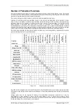
Figure 1.4-4 -Connections for Overall Fault setting Tests by Secondary Injection
1.4.4 Current
transformer ratio and polarity tests
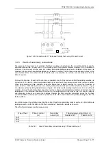
Remove the trip links at both ends of the feeder. Connect ammeters in the current transformer secondary leads at
each end in turn, as shown in Figure 1.4-5. Pass three phase load current through the primary and check the ratio
of each current transformer by comparing the secondary current in each phase with the corresponding primary
current. Check the polarity of the current transformers; the reading of ammeter X in the neutral circuit should be
negligible compared with the secondary phase-currents. Some current may exist in the neutral circuit due to
unbalance of primary load current and/or secondary burden.

