7PG2113/4/5/6 Commissioning & Maintenance
©2012 Siemens Protection Devices Limited
Chapter 6 Page 17 of 77
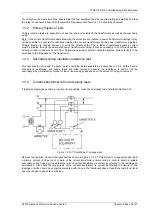
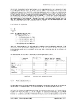
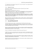
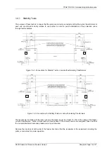
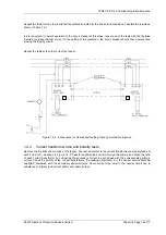
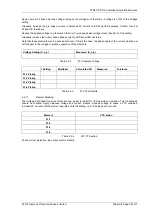
Figure 1.4-5 -Connections for CT Ratio and Polarity Tests using 3P Load Current
1.4.5 Check of secondary connections
The purpose of these tests is to establish that the secondary wiring between the current-transformers and the
summation-transformer at each end is in accordance with the particular diagram supplied for the installation.
However, if load-current is to be used it is unlikely that actual setting-values can be obtained in this case it is
considered reasonable that suitable readings can be taken to confirm that the feeder ends behave similarly for the
same fault-condition. Care should be taken that there is a reasonable value of load current available i.e. 25% to
50% of nominal.
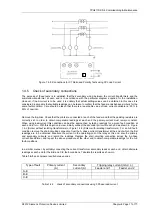
Remove the trip-links. Check that the pilots are connected at each of the feeder and that the padding resistors are
correctly set. In order to obtain comparable readings at each end the primary-current must remain constant.
When using load-current this condition can best be approached by taking readings for a given fault-condition at
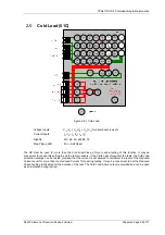
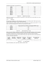
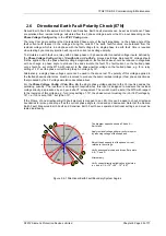
each end in turn. With this objective in view, initially connect the secondary circuit at each end as shown in Figure
1.4-2 (Solkor without isolating transformers) or Figure 1.4-3 (Solkor with isolating transformers). For an A-E fault-
condition remove the short-circuiting connection from the A phase current-transformer at the end of which the first
readings are to be obtained. Measure the current in the operating-coil of the relay at this end, also the primary
and secondary currents, and record the readings. Replace the short-circuiting connection across the A phase
current-transformer, and repeat the above procedure at the other end to obtain comparable readings for the A-E
fault-conditions.
In a similar manner, by suitably connecting the current-transformer secondary leads at each end, obtain alternate
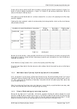
readings at each end for the B-E and C-E fault-conditions. Tabulate the results as shown in
Table
1.4-3
and compare results between ends.
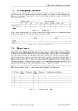
Tripping relay current (mA d.c.)
Type of fault
Primary current
(A)
Secondary
current (A)
Feeder end 1
Feeder end 2
A-E
B-E
C-E
Table 1.4-3
check of secondary connections using 3 Phase load current

