


7PG2113/4/5/6 Commissioning & Maintenance
©2012 Siemens Protection Devices Limited
Chapter 6 Page 22 of 77
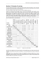
It should be considered that where several overlapping elements are used simultaneously, the overall protection
operate time may be dependent on the operation of different individual elements at the various levels of applied
current or voltage. The resulting composite characteristic may be tested by enabling all of the relevant applicable
elements or the element operations can be separated or disabled and tested individually.
All relay settings should be checked before testing begins. It is recommended that the relay settings are extracted
from the relay using Reydisp Evolution software and a copy of these settings is stored for reference during and
after testing. It may be necessary to disable some protection functions during the testing of other functions to
allow unambiguous results to be obtained.
Care must be taken to reset or re-enable any settings that have been temporarily altered during the testing before
the relay can be put into service. At the end of testing the relay settings should be compared to the file extracted
at the start to ensure that errors have not been introduced.
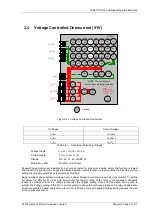
2.1
Current Differential (87)
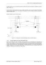
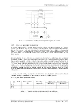
The Current Differential function should be tested in conjunction with the CT polarity and Pilot tests
and is described in section 1.4 above.
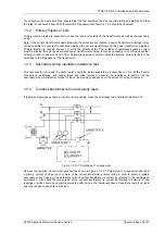
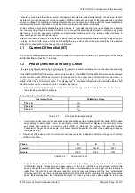
2.2
Phase Directional Polarity Check
If the relay has Directional Overcurrent elements, the common direction polarising can be checked independently
from the individual overcurrent elements and their settings.
In the INSTRUMENTS MODE display, indication is provided in the DIRECTIONAL METERS menu which displays
current direction under
P/F Dir
as forward or reverse based on the output states of the directional elements, i.e.
whether they see forward current, reverse current or neither for each pole with respect to the
67 Char Angle
setting in the
Phase Overcurrent
menu.
This display and the equivalent Measured and Calculated Earth Fault
direction meters can be used as an aid to commissioning testing.
1.
Check the direction of each pole in turn by connecting to the appropriate terminals. The table below
shows
the polarising quantity for each pole.
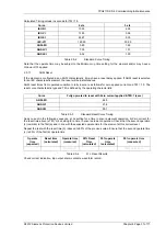
Connections for Directional Polarity
Overcurrent pole
Polarising voltage
Phase
A
V
BC
Phase
B
V
CA
Phase
C
V
AB
Table 2.2-1
Directional Polarising Voltages
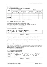
2.
Inject single phase rated current and apply single phase-phase rated voltage at the Char Angle (MTA) phase
angle setting, to each phase in turn. For each pole, monitor the directional display in the instrument menu
and check that indication of forward current (FWD) is displayed. To achieve the required forward
Characteristic Angle, the phase angle of the current should be greater than that of the polarising voltage by
the angle setting.
3. Repeat all of the above with the current connections reversed. Indication should now be given of reverse
(REV) current flow.
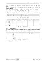
Phase A
B
C
Forward
FWD FWD FWD
Reverse
REV REV REV
Table 2.2-2
Directional Check
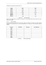
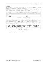
4. Apply balanced 3 phase rated voltage and current with Vbc voltage as a 0deg reference and Ia at the
characteristic angle. Increase current phase angle until the ‘Fwd’ indication is extinguished. Record this
angle in the table below (Forward lead DO). Continue to increase/decrease the angle until the instrument
reads ‘Rev’. Record the angle (Reverse lead PU). Reduce the current angle until the ’Rev’ extinguishes
(Reverse lead DO). and the ‘Fwd’ subsequently returns (Forward lead PU), recording the angles. Repeat the
above tests, starting from the Characteristic Angle, but reducing the current phase angle to record the


