7PG2113/4/5/6 Commissioning & Maintenance
©2012 Siemens Protection Devices Limited
Chapter 6 Page 28 of 77
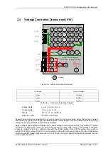
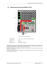
Apply nominal 3 phase balanced voltage. Increase the voltage such that the a-b voltage is 110% of the Voltage
setting
Gradually increase the a-b phase current or balanced 3P current until Pickup LED operates. Confirm result of
Phase O/C test above.
Reduce the applied voltage to a level such that V
12
(V
AB
) phase-phase voltage is less than 90% of the setting.
Gradually increase the I
12
(I
AB
) phase-phase current until Pickup LED operates.
Note that these elements may be set as directional. If this is the case, the phase angle of the current must be set
with respect to the voltage to produce operation of the elements.
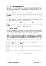
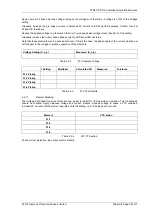
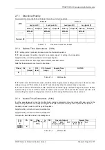
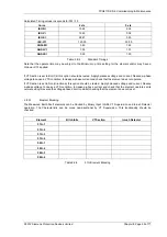
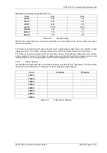
Voltage Setting (V, p-p)
Measured (V, p-p)
Table 2.4-2
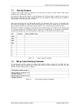
51V Operate Voltage
I Setting
Multiplier
Calculated PU
Measured
Tolerance
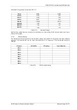
51-1 Pickup
51-2 Pickup
51-3 Pickup
51-4 Pickup
Table 2.4-3
51V Test Results
2.4.1.1 Element
Blocking
The Voltage Controlled Overcurrent function can be set to Inhibit for VT Supervision operation. This functionality
should be checked. Apply balanced voltage and current. Reduce a-phase voltage to cause a VTS condition.
Increase 3P current until the element operates at its full setting, i.e. 51V settings are not used.
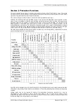
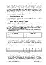
Element VTS
action
51-1
51-2
51-3
51-4
Table 2.4-4
51V VTS action
Check correct indication, trip output, alarm contacts.

