


7PG2113/4/5/6 Commissioning & Maintenance
©2012 Siemens Protection Devices Limited
Chapter 6 Page 74 of 77
6.3.2 Secondary wiring insulation resistance tests
Check the insulation resistance of the secondary wiring as described in the appropriate Operating
Recommendations
.
6.3.3 Pilot
tests
Before doing these tests, ensure that the pilot supervision relay and the transformer-rectifier supervision supply
until are disconnected from the pilots.
Follow the procedure described in the appropriate Operating Recommendations to check the pilot
Insulation resistance, the pilot loop resistance, the correctness of the pilot connections and to select a
suitable value of padding resistor.
6.3.4 C.T. ratio and polarity
Check the current transformers for ratio and polarity as described in the appropriate Operating
Recommendations.
6.3.5 Overall fault setting tests
Fitting pilot supervision to Solkor R of Rf protection affects the overall fault setting. The change in setting is
influenced by several factors, eg. whether the relay is connected in the Solkor R or Solkor Rf mode, whether
isolating transformers are fitted, the value of pilot capacitance current and in some cases the end from which the
fault is fed.
As a general guide for Solkor Rf protection, one could expect the fault setting to increase by between 20 to 50%.
For Solkor R protection (or Solkor Rf protection connected in the Solkor R mode) a similar increase in setting can
be expected at the local end but the remote end setting decreases and both local and remote ends will trip at
approximately the same value.
Due to this variation in fault setting, it is most important that the tests described in the Operating
Recommendations under the heading “Overall fault setting tests” should first of all be done without the pilot
supervision in service. This will not only check the basic fault setting but also confirm that the connections to the
summation transformer at each end of the feeder are correct thus ensuring that the protection will stabilise
correctly for external faults.
At the supervision receive end disconnect the supervision receive relays from the pilots and connect temporary
links in the pilots to complete the pilot loop.
Do the overall fault setting tests at both ends of the feeder as described in the appropriate section of the
Operating Recommendations.
If guard relays are fitted and sufficient test current is available the setting of the guard relays may also be checked
by primary injection.
If it is convenient to permit operation of the circuit breaker at this stage, repeat one of the tests with the trip links
inserted. If guard relays are fitted check that the circuit breaker will not trip until both the guard relay and Solkor
relay have operated.
At the conclusion of the tests, remove the temporary links from the pilots and re-connect the transformer-rectifier
supply unit and the supervision receive relay in the pilot loop.
The pilot supervision supply may be switched on and, if desired, the overall fault settings re-checked with the
supervision equipment in service. Tests of pilot supervision relays
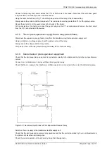
6.3.6 Check of pilots supervision receive relay
Disconnect the pilot supervision receive relay from the pilots and using the test circuit shown in Fig 6 check the
pick-up and drop-off value of the relay.
The pick-up value of the relay should not exceed 3.5 milli-amperes.
The drop-off value of the relay should be less than 1.5 milli-amperes.
6.3.7 Test of guard relays (where fitted)
If it has not been possible to check the operation of the guard relays by primary injection then the following tests
should be done.


