7PG2113/4/5/6 Commissioning & Maintenance
©2012 Siemens Protection Devices Limited
Chapter 6 Page 4 of 77
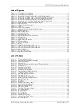
List of Figures
Figure 1.3-1 CT Polarity test 1 arrangement............................................................................................................ 9
Figure 1.3-2 CT Polarity test 2 arrangement.......................................................................................................... 10
Figure 1.4-1 -Connections for Overall Fault setting Tests by Primary Injection ..................................................... 13
Figure 1.4-2 -Connections for Stability Tests on Load without Isolating Transformers .......................................... 14
Figure 1.4-3 -Connections for Stability Tests on Load with Isolating Transformers ............................................... 14
Figure 1.4-4 -Connections for Overall Fault setting Tests by Secondary Injection................................................. 16
Figure 1.4-5 -Connections for CT Ratio and Polarity Tests using 3P Load Current ............................................... 17
Figure 2.2-1 Directional Phase Fault Boundary System Angles............................................................................. 23
Figure 2.3-1 Phase Overcurrent............................................................................................................................. 24
Figure 2.4-1 Voltage Controlled Overcurrent ......................................................................................................... 27
Figure 2.5-1 Cold Load .......................................................................................................................................... 29
Figure 2.5-2 Cold Load Logic diagram................................................................................................................... 30
Figure 2.6-1 Directional Earth Fault Boundary System Angles .............................................................................. 32
Figure 2.7-1 Derived Earth Fault............................................................................................................................ 33
Figure 2.8-1 Measured Earth Fault ........................................................................................................................ 37
Figure 2.9-1 Sensitive Earth Fault.......................................................................................................................... 41
Figure 2.10-1 Restricted Earth Fault ...................................................................................................................... 45
Figure 2.11-1 Negative Phase Sequence Overcurrent .......................................................................................... 47
Figure 2.12-1 Undercurrent.................................................................................................................................... 50
Figure 2.13-1 Thermal Overload ............................................................................................................................ 52
Figure 2.14-1 Phase Under/Over Voltage.............................................................................................................. 54
Figure 2.15-1 NPS Overvoltage ............................................................................................................................. 56
Figure 2.16-1 Neutral Overvoltage......................................................................................................................... 58
Figure 3.1-1 CB Fail............................................................................................................................................... 60
Figure 3.2-1 Voltage Transformer Supervision ...................................................................................................... 62
Figure 3.3-1 Current Transformer Supervision 7PG2113/5 ................................................................................... 64
Figure 3.3-2 Current Transformer Supervision 7PG2114/6 ................................................................................... 65
Figure 3.4-1 Broken Conductor.............................................................................................................................. 66
Figure 3.5-1 Trip Circuit Supervision...................................................................................................................... 68
Figure 3.6-1 Magnetising Inrush Detector.............................................................................................................. 69
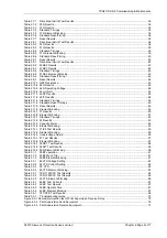
List of Tables
Table 1.3-1
C.T ratio and polarity tests............................................................................................................... 10
Table 1.3-2
Resistance and capacitance limitations........................................................................................... 11
Table 1.4-1
Test of fault settings ........................................................................................................................ 13
Table 1.4-2
stability tests.................................................................................................................................... 15
Table 1.4-3
check of secondary connections using 3 Phase load current .......................................................... 17
Table 1.5-1
AC meter text .................................................................................................................................. 18
Table 1.5-2
Sequence Current meters ............................................................................................................... 18
Table 1.6-1
Binary Inputs test results ................................................................................................................. 18
Table 1.7-1
Binary Output Test Results.............................................................................................................. 20
Table 1.8-1
Case Shorting Contacts Test Results.............................................................................................. 20
Table 1.8-1
Protection Function Conflicts........................................................................................................... 21
Table 2.2-1
Directional Polarising Voltages........................................................................................................ 22
Table 2.2-2
Directional Check ............................................................................................................................ 22
Table 2.2-3
Directional Limits Test Results ........................................................................................................ 23
Table 2.2-4
Minimum polarising Voltage Results ............................................................................................... 23
Table 2.2-5
2 out of 3 Logic Test........................................................................................................................ 24
Table 2.3-1
50 Results ....................................................................................................................................... 25
Table 2.3-2
51 Results ....................................................................................................................................... 25
Table 2.3-3
Standard Timing Curve values ........................................................................................................ 25
Table 2.3-4
50 Element Blocking Results........................................................................................................... 26
Table 2.3-5
ANSI reset standard values............................................................................................................. 26
Table 2.3-6
Reset Time Results ......................................................................................................................... 26
Table 2.4-1
Directional Polarising Voltages........................................................................................................ 27
Table 2.4-2
51V Operate Voltage....................................................................................................................... 28
Table 2.4-3
51V Test Results ............................................................................................................................. 28
Table 2.4-4
51V VTS action ............................................................................................................................... 28
Table 2.5-1
51c Test Results.............................................................................................................................. 30
Table 2.5-2
Standard Curve Timing.................................................................................................................... 31
Table 2.5-3
Standard ResetCurve Timing .......................................................................................................... 31
Table 2.5-4
51c Reset Results .......................................................................................................................... 31


