


7PG2113/4/5/6 Commissioning & Maintenance
©2012 Siemens Protection Devices Limited
Chapter 6 Page 18 of 77
1.5
AC Energising Quantities
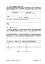
Voltage and current measurement for each input channel is displayed in the Instrumentation Mode sub-menus,
each input should be checked for correct connection and measurement accuracy by single phase secondary
injection at nominal levels. Ensure that the correct instrument displays the applied signal within limits of the
Performance Specification.
Applied Current……………………
Applied Voltage………….
I
A
I
B
I
C
I
G/SEF
Tol V
A
/V
AB
V
B
/V
BC
V
C
/V
CB
Tol
Secondary
Primary
Table 1.5-1
AC meter text
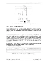
Apply 3 phase balanced Current and Voltage at nominal levels and ensure that the measured Zero Phase
Sequence and Negative Phase Sequence quantities are approximately zero.
ZPS NPS
Voltage
Current
Table 1.5-2
Sequence Current meters
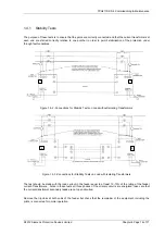
1.6
Binary
Inputs
The operation of the binary input(s) can be monitored on the ‘Binary Input Meters’ display shown in ‘Instruments
Mode’. Apply the required supply voltage onto each binary input in turn and check for correct operation.
Depending on the application, each binary input may be programmed to perform a specific function; each binary
should be checked to prove that its mapping and functionality is as set as part of the Scheme Operation tests.
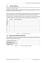
Where the pick-up timers associated with a binary input are set these delays should be checked either as part of
the scheme logic or individually. To check a binary pick-up time delay, temporarily map the binary to an output
relay that has a normally open contact. This can be achieved in the Output Matrix sub-menu by utilising the
BI n
Operated
settings. Use an external timer to measure the interval between binary energisation and closure of the
output contacts. Similarly, to measure the drop-off delay, map to an output relay that has a normally closed
contact, time the interval between binary de-energisation and closure of the output contacts.
Note. The time measured will include an additional delay, typically less than 20ms, due to the response time of
the binary input hardware, software processing time and the operate time of the output relay.
BI Tested DO
Delay
Measured PU
Delay
Measured
Notes (method of initiation)
1
2
3
4
5
6
Table 1.6-1
Binary Inputs test results


