


7PG2113/4/5/6 Solkor Applications Guide
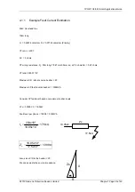
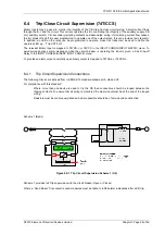
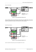
6.4.2 Close Circuit Supervision Connections
R
+
CLOSE
COIL
52a
52b
-
Circuit
Breaker
BI
+ve
-ve
BO 1
BO n
Remote
Alarm
BO
R
CLOSE CCT n FAIL
7SR24
H5 Scheme Notes:
BI = 19V (30, 48, 110, 220V supply)
BI = 88V (110, 220V supply)
R = 3K3 typical
Figure 6.4-4 Close Circuit Supervision Scheme
Close circuit supervision with the circuit breaker Open or Closed.
6.5
Inrush Detector (81HBL2)
This element detects the presence of high levels of 2nd Harmonic current which is indicative of transformer Inrush
current at switch-on. These currents may be above the operate level of the overcurrent elements for a short
duration and it is important that the relay does not issue an incorrect trip command for this transient network
condition.
If a magnetic inrush condition is detected operation of the overcurrent elements can be blocked.
Calculation of the magnetising inrush current level is complex. However a ratio of 20% 2
nd
Harmonic to
Fundamental current will meet most applications without compromising the integrity of the Overcurrent protection.
There are 3 methods of detection and blocking during the passage of magnetising inrush current.
Phase
Blocking only occurs in those phases where Inrush is detected.
Large, Single Phase Transformers – Auto-transformers.
Cross
All 3-phases are blocked if Inrush is detected in any phase.
Traditional application for most Transformers but can give delayed operation for Switch-
on to Earth Fault conditions.
Sum
Composite 2nd Harmonic content derived for all 3-phases and then compared to
Fundamental current for each individual phase.
Provides good compromise between Inrush stability and fast fault detection.
Table 6-4
Magnetic Inrush Bias
6.6
Broken Conductor / Load Imbalance (46BC)
Used to detect an open circuit condition when a conductor breaks or a mal-operation occurs in phase segregated
switchgear.
There will be little or no fault current and so overcurrent elements will not detect the condition. However the
condition can be detected because there will be a high content of NPS (unbalance) current present.
An NPS / PPS ratio > 50% will result from a Broken Conductor condition.
Operation is subject to a time delay to prevent operation for transitory effects.
©2010 Siemens Protection Devices Limited
Chapter 7 Page 48 of 49


