


7PG2113/4/5/6 Commissioning & Maintenance
©2012 Siemens Protection Devices Limited
Chapter 6 Page 48 of 77
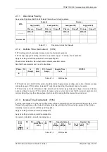
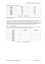
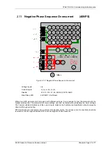
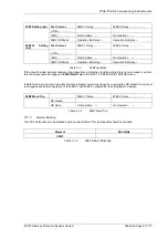
2.11.1 Definite Time NPS Overcurrent (46DT)
If DTL setting is small, gradually increase current until element operates.
If DTL is large apply 0.9x setting, check for no operation, apply 1.1x setting, check operation
Apply 2x setting current if possible and record operating time
Phase Is
(Amps)
DTL
(sec)
P.U. Current
Amps
Tolerance Operate
Time
2 x Is
Tolerance
NPS
Table 2.11-1
46DT Results
Check correct indication, trip output, alarm contacts, waveform record.
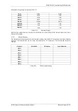
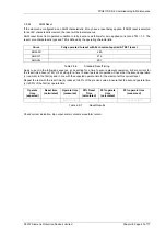
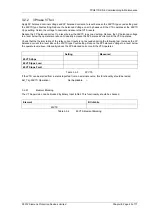
2.11.2 Inverse Time NPS Overcurrent (46IT)
It will be advantageous to map the function being tested to temporarily drive the relevant Pickup output in the
Pickup Config
sub-menu in the
Output Config
menu as this will allow the Pick-up led to operate for the function.
Gradually increase current until Pickup LED operates.
Apply 2x setting current and record operating time,
Apply 5x setting current and record operating time.
Compare to calculated values for operating times
Operate Current
Operate Time
Ph.
P.U.
(Amps)
D.O.
(Amps)
Tol
2 x Is
(sec)
5 x Is
(sec)
Tol
P.U.
D.O.
&
TIMING
TESTS
NPS
Dir Char.
(NI EI VI LTI,
DTL)
Is
(A)
TM
Table 2.11-2
46IT Results
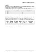
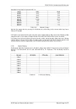
Calculated Timing values in seconds for TM =1.0
Curve
2 xIs
5 xIs
IEC-NI 10.03
4.28
IEC-VI 13.50
3.38
IEC-EI 26.67
3.33
IEC-LTI 120.00
30.00
ANSI-MI 3.80
1.69
ANSI-VI 7.03
1.31
ANSI-EI 9.52
1.30
Table 2.11-3
Standard Timings
Note that the operate time may be subject to the
Minimum op time
setting for the element and/or may have a
Follower DTL
applied.


