7PG2113/4/5/6 Commissioning & Maintenance
©2012 Siemens Protection Devices Limited
Chapter 6 Page 26 of 77
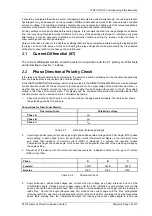
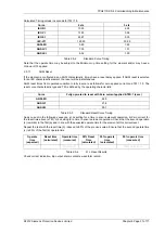
2.3.2.1 Element
Blocking
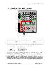
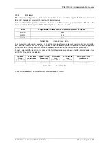
The Phase Overcurrent elements can be blocked by Binary Input Inhibit, VT Supervision and Inrush Detector
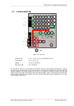
operation, as well as 79 Autoreclose settings for Inst/Delayed. The Characteristic can be modified by Cold Load
(51-n only) and Voltage Controlled Overcurrent and can be made non-directional by VT Supervision. This
functionality should be checked.
Element
BI Inhibits
VTS action
Inrush Detector
79 Autoreclose
51-1
51-2
51-3
51-4
50-1
50-2
50-3
50-4
Table 2.3-4
50 Element Blocking Results
2.3.2.2
ANSI Reset
If the element is configured as an ANSI characteristic, it may have an ANSI (decaying) reset delay applied. If
ANSI reset is selected for an IEC characteristic element, the reset will be instantaneous.
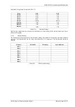
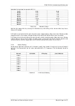
ANSI reset times from operated condition to fully reset are as follows for zero applied current and Time multiplier
(TM) = 1.0. The reset curve characteristic type and TM is defined by the operating characteristic.
Curve
Fully operated to reset with Zero current applied & TM=1 (secs)
ANSI-MI
4.85
ANSI-VI
21.6
ANSI-EI
29.1
Table 2.3-5
ANSI reset standard values
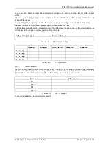
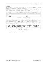
Apply current in the following sequence, a) 2x setting for a time to ensure element operation, b) Zero current for
the reset time above (xTM), c) 2x setting for a time to ensure element operation. Check that the second operation
(c) is similar to the first (a) and in line with the expected operate time for the element at this current level.
Repeat the test with the reset time (b) reduced to 50% of the previous value. Ensure that the second operate time
(c) is 50% of the first (a) operate time.
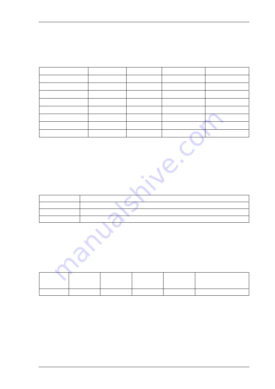
Table 2.3-6
Reset Time Results
Check correct indication, trip output, alarm contacts, waveform record.
Operate
time
(expected)
Reset time
(calculated)
Operate time
(measured)
50% Reset
Time
(calculated)
50% operate
time
(calculated)
50% operate time
(measured)
First test (c)
Second Test (c)

