7PG2113/4/5/6 Data Communications
©2010 Siemens Protection Devices Limited
Chapter 4 Page 34 of 38
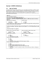
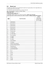
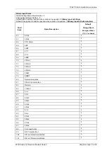
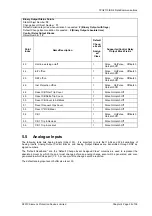
Binary Output Status Points
Static Object Number:
10
Change Event Object Number:
11
Default Variation reported when variation 0 requested:
2 (Binary Output with flags)
Default Change Event variation 0 requested:
2 (Binary Output absolute time)
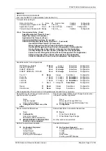
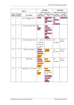
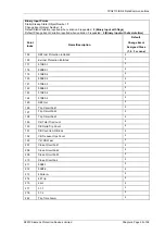
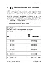
Control Relay Output Blocks
Object Number:
12
Point
Index
Name/Description
Default
Chang
e Event
Assign
ed
Class
Supported Control Relay
Output Block Fields
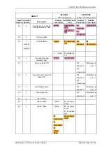
43
Hot line working on/off
1
Pulse On/Pulse Off/Latch
On/Latch Off
44
E/F
off/on
1
Pulse On/Pulse Off/Latch
On/Latch Off
45
SEF
off/on
1
Pulse On/Pulse Off/Latch
On/Latch Off
46
Inst Protection off/on
1
Pulse On/Pulse Off/Latch
On/Latch Off
48
Reset CB Total Trip Count
1
Pulse On/Latch Off
49
Reset CB Delta Trip Count
1
Pulse On/Latch Off
50
Reset CB Count to AR Block
1
Pulse On/Latch Off
51
Reset Frequent Ops Count
1
Pulse On/Latch Off
53
Reset I^2t CB Wear
1
Pulse On/Latch Off
54
CB
1
1
Pulse On/Pulse Off/Latch
On/Latch Off
55
CB 1 Trip & Reclose
1
Pulse On/Latch Off
56
CB 1 Trip & Lockout
1
Pulse On/Latch Off
5.5
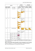
Analogue Inputs
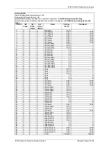
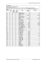
The following table lists Analog Inputs (Object 30). It is important to note that 16-bit and 32-bit variations of
Analog Inputs, Analog Output Control Blocks, and Analog Output Statuses are transmitted through DNP as
signed numbers.
The “Default Deadband,” and the “Default Change Event Assigned Class” columns are used to represent the
absolute amount by which the point must change before an analog change event will be generated, and once
generated in which class poll (1, 2, 3, or none) will the change event be reported.
The default analog input event buffer size is set 30.

