


7PG2113/4/5/6 Commissioning & Maintenance
©2012 Siemens Protection Devices Limited
Chapter 6 Page 11 of 77
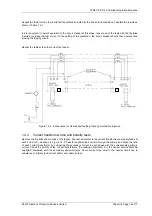
With the pilots disconnected at both ends of the feeder, join the cores together at one end and measure the pilot-
loop resistance from the other end. If the pilot loop resistance is less than the standard value for the particular
arrangement being used (See Table 1.3-2) add padding resistance at each end. If isolating transformers are
being used, choose the secondary tap to suit the measured pilot resistance. Thus for a pilot loop resistance lower
than 440 ohms choose tap T1; for a pilot loop resistance between 440 ohms and 880 ohms choose tap T2; For a
pilot loop resistance between 880 ohms and 1760 ohms choose tap F2. This will ensure that pilot capacitance will
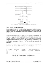
have a minimal effect upon the relay fault setting. The padding resistor comprises five series-connected sections,
each section having a short-circuiting link. The values of resistance in the sections are 35 ohms, 65 ohms, 130
ohms, 260 ohms and 500 ohms. One or more sections can be inserted by removing the appropriate link or links
which are located on the link-board. Choose the same value at each end.
It should be as near as possible to:
T
Rp
Sv
2
−
where Sv = Standard Value from Table 2
Rp =Pilot Loop Resistance
T = Isolating Transformer Tap
= 1.0 if no isolating transformer fitted
= 1.0 for isolating transformer tapping F2
= 0.5 for isolating transformer tapping T2
= 0.25 for isolating transformer tapping T1
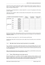
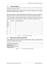
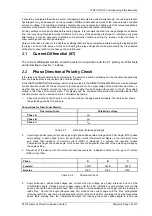
Table 1.3-2
shows the standard pilot loop resistance and maximum inter-core capacitance permissible for the
various arrangements of Solkor. When isolating transformers are fitted it is recommended that, as a general rule,
the tap chosen should be the one which allows the maximum value of pilot capacitance for the measured pilot
loop resistance.
The resistors are inserted by removing the shorting plug and fitting in the park position.
Transformer
terminal
Transformer tap
value (T)
Standard value of
pilot loop resistance
(S.V.)
Maximum
capacitance
between cores
μ
F
Solkor R
-
1.0
1000
2.5
Solkor Rf without
isolating
transformers
- 1.0
2000
0.8
F2 1.0 1760
1
T2 0.5 880 2
Solkor Rf with
isolating
transformers
T1 0.25
440 4
Table 1.3-2
Resistance and capacitance limitations
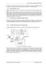
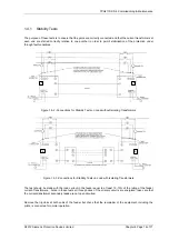
1.3.7 Pilot connection check
If isolating transformers are not fitted check that relay terminals E17 at both ends of the feeder are connected by
one pilot core and that relay terminals 18 at both ends of the feeder are connected by the other pilot core.
This is achieved by disconnecting the pilots at both ends, earthing one core at the remote end and measuring the
resistance to earth of each core at the local end. The pilot core giving the lower reading is the one which is
earthed at the remote end. If isolating transformers are fitted check that transformers terminals S2 at both ends of
the feeder are connected by one pilot core. Check that the other pilot core connects transformer terminal F2, T2


