7PG2113/4/5/6 Commissioning & Maintenance
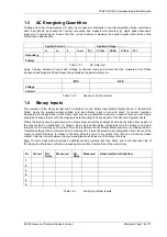
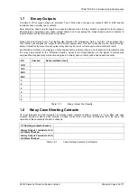
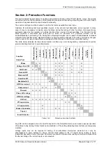
©2012 Siemens Protection Devices Limited
Chapter 6 Page 13 of 77
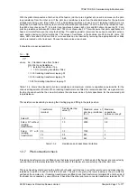
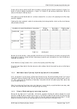
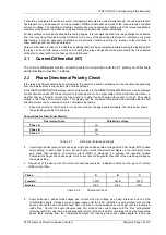
Measured fault setting
(amps)
Fault settings
Solkor Rf without isolating
transformers
Solkor Rf with isolating
transformers
Primary
current
Secondary
current
Relay
operating
current
m/amps D.C.
R mode
Rf mode
R mode
Rf mode
Typ
e of
fault
At
end
1
At
end
2
At
end
1
At
end
2
At
end
1
At
end
2
Type
of
fault
N1
tap
N
tap
N1
tap
N
tap
N1
tap
N
tap
N1
tap
N
tap
A-E A-E 16 22 18 25 22 31 25 35
B-E
B-E
18
27.5
21
32
22
31
30
44
C-E C-E 22 37 25 42 31 52 35 59
A-B
A-B 110
125
155
177
A-C
A-C 110
125
155
177
C-A
C-A 55
62
77.5
88.5
3
P
3
P 63
72
89
101
Table 1.4-1
Test of fault settings
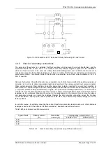
If it is convenient to permit operation of the circuit breaker at this stage, repeat one of the tests with the trip links
inserted. Increase the primary current to the setting of the protection; the circuit breaker should then operate thus
proving the tripping circuit.
Repeat the tests at the other end of the feeder.
When all the tests have been completed at both ends of the feeder, compare results between ends. Check that
the most sensitive earth fault setting at each end refers to the same phase, i.e. the red phase, the next sensitive
the Yellow phase and the least sensitive the Blue phase.
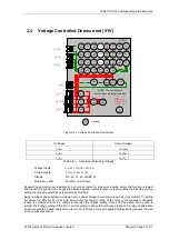
It should be noted that primary fault settings vary slightly with the current transformers used and the capacitance
of the pilots. With average current transformers the fault settings at zero pilot capacitance are as given in Table 3.
Values are expressed as percentages of relay rating.
Fault settings will be practically unchanged for pilot capacitance values between zero and approximately 80% of
the maximum capacitance values specified in Table 1.3-2
.
Values of pilot capacitance higher than this have the
effect of increasing the fault settings.
E
E
A
B
C
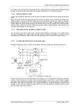
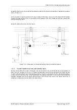
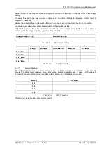
Figure 1.4-1 -Connections for Overall Fault setting Tests by Primary Injection


