


7PG2113/4/5/6 Commissioning & Maintenance
©2012 Siemens Protection Devices Limited
Chapter 6 Page 12 of 77
or T1 (depending upon which tapping is being used) at one end of the feeder to the equivalent transformer
terminal at the other end of the feeder.
1.3.8 Putting into Service
After tests have been performed satisfactorily the relay should be put back into service as follows:-
Remove all test connections.
Replace all secondary circuit fuses and links, or close m.c.b.
Ensure the Protection Healthy LED is on, steady, and that all LED indications are correct. If necessary press
CANCEL
until the Relay Identifier screen is displayed, then press
TEST/RESET
to reset the indication LEDs.
The relay meters should be checked in Instruments Mode with the relay on load.
The relay settings should be downloaded to a computer and a printout of the settings produced. The installed
settings should then be compared against the required settings supplied before testing began. Automated setting
comparison can be carried out by Reydisp using the
Compare Settings Groups
function in the
Edit
menu. Any
modified settings will be clearly highlighted.
Make a final inspection to ensure that the equipment is ready for automatic tripping. In particular check that the
metering test-link of each relay is firmly inserted and that all connections are tight. Finally, insert the tripping links,
the protection is then ready for service.
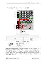
1.4
Current Differential (87)
If testing by single-phase primary-injection is not possible, make the alternative tests described on page 4.
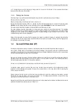
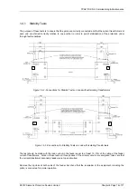
The purpose of these tests is to establish the overall fault-settings of the protection and also to establish that the
secondary wiring between the current-transformers and the summation transformer at each end is in accordance
with the particular diagram supplied for the installation.
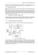
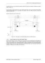
Remove the trip-links but ensure that the padding resistors are correctly set. Connect the test-supply initially to
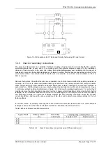
simulate a Red-earth fault-condition as shown in Figure 1.4-1and perform the tests in the following sequence.
Test set requirements of section 1.2.3 should be observed.
Connect a d.c. milli-ammeter in the operating circuit of each relay as shown in Figure 1.4-1
.
On Epsilon cased relays, to perform this test, 4mm ‘banana’ plugs connected to the multipurpose ammeter
(selected to DC milliamps) are required. Observe the polarity shown on the relay label. After connecting the
meter, remove the test link.
Slowly increase the test current until the local relay operates and record the primary and secondary currents.
Check that the relay operating current is approximately 11 to 12 milliamperes and that the current in the relay
operating circuit at the remote end is of the same order.
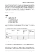
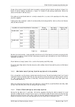
Repeat the test for the other earth fault conditions and also for the phase fault conditions if sufficient test current is
available. Tabulate the results as shown in
Table 1.4-1
.


