SECTION 7 - BASIC TROUBLESHOOTING, ELECTRICAL INFORMATION, & SCHEMATICS
3121827
– JLG Lift –
7-15
.
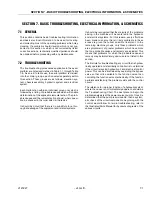
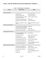
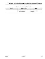
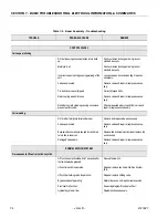
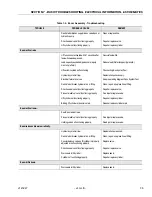
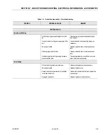
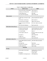
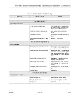
Table 7-5. Hydraulic System - Troubleshooting
TROUBLE
PROBABLE CAUSE
REMEDY
HYDRAULIC SYSTEMS - GENERAL.
Hydraulic pump noisy.
Air entering system through broken line or fitting.
(Suction Side.)
Repair or replace line or fitting.
Air bubbles in oil. (Reservoir oil too low.
Replenish oil as required.
Suction hose squeezed shut.
Determine cause and repair.
Oil filter dirty.
Replace hydraulic filter.
Wrong type of hydraulic oil.
Replace hydraulic oil.
Pump cavitating. (Vacuum in pump due to oil
starvation.)
Restricted suction line.
Clean, repair, or replace line.
Restricted reservoir air vent.
Clean or replace vent.
Oil viscosity too high.
Drain system and replace with recommended oil.
(Refer to Hydraulic Oils.)
Air leak in suction side of tank.
Repair leak.
System overheating.
Oil viscosity too high.
Drain system and replace with recommended oil.
(Refer to Hydraulic Oils.)
Bypass valve not operating properly.
Repair or replace valve.
Main relief valve set too low.
Reset valve as required.
Hydraulic system oil low.
Replenish oil as necessary.
Port relief set too high.
Reset valve as required.
Restricted or blocked return line.
Repair or replace line.
Pump not delivering oil.
Restricted suction line.
Clean, repair, or replace line.
Air entering system through broken line or fitting.
Repair or replace line or fitting.
Broken pump drive shaft/pump coupling.
Repair or replace pump/pump coupling.
Note: Any time pump or pump drive coupling
is removed coat pump and drive coupling
splines with Lithium Soap Base Grease (TEX-
ACO CODE 1912 OR EQUIVALENT).
Содержание JLG E400AJP
Страница 2: ......
Страница 21: ...SECTION 1 SPECIFICATIONS 3121827 JLG Lift 1 7 Figure 1 2 Operator Maintenance Lubrication Diagram...
Страница 32: ...SECTION 1 SPECIFICATIONS 1 18 JLG Lift 3121827 NOTES...
Страница 42: ...SECTION 2 GENERAL 2 10 JLG Lift 3121827 NOTES...
Страница 54: ...SECTION 3 CHASSIS TURNTABLE 3 12 JLG Lift 3121827 Figure 3 3 Speed Sensor Orientation...
Страница 55: ...SECTION 3 CHASSIS TURNTABLE 3121827 JLG Lift 3 13 Figure 3 4 Frame Mounted Electrical Components Sheet 1 of 2...
Страница 56: ...SECTION 3 CHASSIS TURNTABLE 3 14 JLG Lift 3121827 Figure 3 5 Frame Mounted Electrical Components Sheet 2 of 2...
Страница 60: ...SECTION 3 CHASSIS TURNTABLE 3 18 JLG Lift 3121827 Figure 3 7 Steering Components and Spindles...
Страница 62: ...SECTION 3 CHASSIS TURNTABLE 3 20 JLG Lift 3121827 Figure 3 9 Tilt Sensor Location...
Страница 86: ...SECTION 3 CHASSIS TURNTABLE 3 44 JLG Lift 3121827 Figure 3 16 Swing Components...
Страница 88: ...SECTION 3 CHASSIS TURNTABLE 3 46 JLG Lift 3121827 Figure 3 18 Battery Cable Connections...
Страница 90: ...SECTION 3 CHASSIS TURNTABLE 3 48 JLG Lift 3121827 Figure 3 20 On Board Generator...
Страница 97: ...SECTION 3 CHASSIS TURNTABLE 3121827 JLG Lift 3 55 Figure 3 22 Generator Components...
Страница 100: ...SECTION 3 CHASSIS TURNTABLE 3 58 JLG Lift 3121827 Figure 3 23 Generator System Analyzer Flow Chart...
Страница 116: ...SECTION 3 CHASSIS TURNTABLE 3 74 JLG Lift 3121827 NOTES...
Страница 125: ...SECTION 4 BOOM PLATFORM 3121827 JLG Lift 4 9 Figure 4 8 Jib Platform Components and Attaching Hardware...
Страница 127: ...SECTION 4 BOOM PLATFORM 3121827 JLG Lift 4 11 Figure 4 10 Boom Limit Switches...
Страница 140: ...SECTION 4 BOOM PLATFORM 4 24 JLG Lift 3121827 Figure 4 13 Rotator Counterbalance Valve...
Страница 178: ...SECTION 5 HYDRAULICS 5 24 JLG Lift 3121827 Figure 5 26 HydraForce Cartridge Torque Value Chart...
Страница 179: ...SECTION 5 HYDRAULICS 3121827 JLG Lift 5 25 Figure 5 27 Main Valve Components Prior to S N 62642...
Страница 214: ...SECTION 6 JLG CONTROL SYSTEM 6 34 JLG Lift 3121827 NOTES...
Страница 257: ......

