SECTION 5 - HYDRAULICS
3121827
– JLG Lift –
5-3
5.2 CYLINDERS - THEORY OF OPERATION
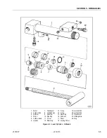
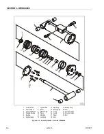
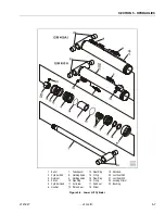
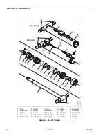
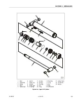
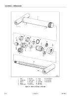
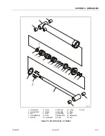
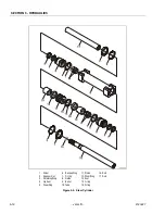
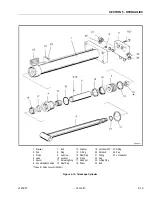
Double Acting Cylinder
(Upper Boom Lift, Mid Boom Lift, Lower Boom Lift, Tele-
scope, Slave, Master, Rotator, and Steer)
A double acting cylinder is one that requires oil flow to
operate the cylinder rod in both directions. Directing oil
(by actuating the corresponding control valve to the pis-
ton side of the cylinder) forces the piston to travel toward
the rod end of the barrel, extending the cylinder rod (pis-
ton attached to rod). When the oil flow is stopped, move-
ment of the rod will stop. By directing oil to the rod side of
the cylinder, the piston will be forced in the opposite direc-
tion and the cylinder rod will retract.
Holding valves are used in the Lift circuits to prevent
retraction of the cylinder rod should a hydraulic line rup-
ture or leak develop between the cylinder and its related
control valve.
5.3 CYLINDER CHECKING PROCEDURES
NOTE:
Cylinder checks must be performed any time a cylin-
der component is replaced or when improper system
operation is suspected.
Cylinder Without Counterbalance Valves
(Steer, and Master Cylinders)
1.
Using all applicable safety precautions, activate
hydraulic system and fully extend cylinder to be
checked. Shut down hydraulic system.
2.
Carefully disconnect hydraulic hose from retract port
of cylinder. There will be initial weeping of hydraulic
fluid which can be caught in a suitable container.
After initial discharge, there should be no further
leakage from the retract port.
3.
Activate hydraulic system, and activate cylinder
extend function.
4.
If cylinder retract port leakage is less than 6-8 drops
per minute, carefully reconnect hose to retract port
and retract cylinder. If leakage continues at a rate of
6-8 drops per minute or more, cylinder repairs must
be made.
5.
With cylinder fully retracted, shut down motor and
carefully disconnect hydraulic hose from cylinder
extend port.
6.
Activate hydraulic system and activate cylinder
retract function. Check extend port for leakage.
7.
If extend port leakage is less than 6-8 drops per min-
ute, carefully reconnect hose to extend port, then
activate cylinder through one complete cycle and
check for leaks. If leakage continues at a rate of 6-8
drops per minute or more, cylinder repairs must be
made.
Cylinders With Single Counterbalance
Valve
(Upper Lift Cylinder)
OPERATE ALL FUNCTIONS FROM GROUND CONTROL STATION
ONLY.
1.
Using all applicable safety precautions, activate
hydraulic system.
WHEN WORKING ON THE UPPER BOOM LIFT CYLINDER RAISE
THE UPPER BOOM TO HORIZONTAL AND PLACE A BOOM PROP
APPROXIMATELY 1 INCH (2.54 CM) BELOW THE MAIN BOOM. IF
WORKING ON LOWER BOOM LIFT CYLINDER, RAISE LOWER
BOOM HALFWAY, FULLY ELEVATE UPPER BOOM AND ATTACH
OVERHEAD CRANE TO THE UPRIGHT FOR SUPPORT, LEAVING
APPROXIMATELY 1 INCH (2.54 CM) OF SLACK IN CHAIN OR
SLING FOR TEST PURPOSES.
2.
After completing the above, shut down hydraulic
system and allow machine to sit for 10-15 minutes.
This is done to relieve pressure in the hydraulic
lines. Carefully remove hydraulic hoses from appro-
priate cylinder port block.
3.
There will be initial weeping of hydraulic fluid, which
can be caught in a suitable container. After the initial
discharge, there should not be any further leakage
from the ports. If leakage continues at a rate of 6-8
drops per minute or more, the following cylinder
repairs must be made. If the retract port is leaking,
the piston is leaking, the piston seals are defective
and must be replaced. If the extend port is leaking,
the counterbalance is defective and must be
replaced.
4.
If no repairs are necessary or when repairs have
been made, carefully reconnect hydraulic hoses to
the appropriate ports.
5.
Remove boom prop/overhead crane, activate
hydraulic system and run cylinder through complete
cycle to check for leaks and operation.
Содержание JLG E400AJP
Страница 2: ......
Страница 21: ...SECTION 1 SPECIFICATIONS 3121827 JLG Lift 1 7 Figure 1 2 Operator Maintenance Lubrication Diagram...
Страница 32: ...SECTION 1 SPECIFICATIONS 1 18 JLG Lift 3121827 NOTES...
Страница 42: ...SECTION 2 GENERAL 2 10 JLG Lift 3121827 NOTES...
Страница 54: ...SECTION 3 CHASSIS TURNTABLE 3 12 JLG Lift 3121827 Figure 3 3 Speed Sensor Orientation...
Страница 55: ...SECTION 3 CHASSIS TURNTABLE 3121827 JLG Lift 3 13 Figure 3 4 Frame Mounted Electrical Components Sheet 1 of 2...
Страница 56: ...SECTION 3 CHASSIS TURNTABLE 3 14 JLG Lift 3121827 Figure 3 5 Frame Mounted Electrical Components Sheet 2 of 2...
Страница 60: ...SECTION 3 CHASSIS TURNTABLE 3 18 JLG Lift 3121827 Figure 3 7 Steering Components and Spindles...
Страница 62: ...SECTION 3 CHASSIS TURNTABLE 3 20 JLG Lift 3121827 Figure 3 9 Tilt Sensor Location...
Страница 86: ...SECTION 3 CHASSIS TURNTABLE 3 44 JLG Lift 3121827 Figure 3 16 Swing Components...
Страница 88: ...SECTION 3 CHASSIS TURNTABLE 3 46 JLG Lift 3121827 Figure 3 18 Battery Cable Connections...
Страница 90: ...SECTION 3 CHASSIS TURNTABLE 3 48 JLG Lift 3121827 Figure 3 20 On Board Generator...
Страница 97: ...SECTION 3 CHASSIS TURNTABLE 3121827 JLG Lift 3 55 Figure 3 22 Generator Components...
Страница 100: ...SECTION 3 CHASSIS TURNTABLE 3 58 JLG Lift 3121827 Figure 3 23 Generator System Analyzer Flow Chart...
Страница 116: ...SECTION 3 CHASSIS TURNTABLE 3 74 JLG Lift 3121827 NOTES...
Страница 125: ...SECTION 4 BOOM PLATFORM 3121827 JLG Lift 4 9 Figure 4 8 Jib Platform Components and Attaching Hardware...
Страница 127: ...SECTION 4 BOOM PLATFORM 3121827 JLG Lift 4 11 Figure 4 10 Boom Limit Switches...
Страница 140: ...SECTION 4 BOOM PLATFORM 4 24 JLG Lift 3121827 Figure 4 13 Rotator Counterbalance Valve...
Страница 178: ...SECTION 5 HYDRAULICS 5 24 JLG Lift 3121827 Figure 5 26 HydraForce Cartridge Torque Value Chart...
Страница 179: ...SECTION 5 HYDRAULICS 3121827 JLG Lift 5 25 Figure 5 27 Main Valve Components Prior to S N 62642...
Страница 214: ...SECTION 6 JLG CONTROL SYSTEM 6 34 JLG Lift 3121827 NOTES...
Страница 257: ......

