SECTION 3 - CHASSIS & TURNTABLE
3121827
– JLG Lift –
3-63
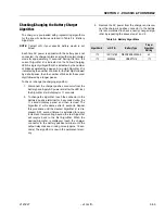
Start Battery
The RBS requires a 12V lead-acid start battery (not sup-
plied with the system), which provides starting power and
power for the RBS controls.
This battery is charged by the engine dynamo and
dynamo regulator when the engine is running.
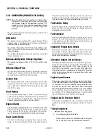
Engine Starter
The engine is equipped with a 12VDC starter, which pro-
vides the mechanical power to crank the engine. Electrical
power for the starter is provided by the start battery.
The starter is energized by the start control relay.
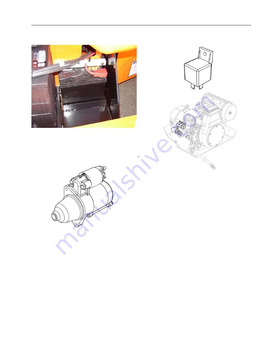
Start Control Relay
The start control relay energizes the solenoid of the
engine starter and the pull coil of the engine fuel solenoid.
The start control relay is energized by the engine/genera-
tor controller from pin J2-4.
The start control relay is located on the fuel solenoid
bracket on the right side of the engine.
Содержание JLG E400AJP
Страница 2: ......
Страница 21: ...SECTION 1 SPECIFICATIONS 3121827 JLG Lift 1 7 Figure 1 2 Operator Maintenance Lubrication Diagram...
Страница 32: ...SECTION 1 SPECIFICATIONS 1 18 JLG Lift 3121827 NOTES...
Страница 42: ...SECTION 2 GENERAL 2 10 JLG Lift 3121827 NOTES...
Страница 54: ...SECTION 3 CHASSIS TURNTABLE 3 12 JLG Lift 3121827 Figure 3 3 Speed Sensor Orientation...
Страница 55: ...SECTION 3 CHASSIS TURNTABLE 3121827 JLG Lift 3 13 Figure 3 4 Frame Mounted Electrical Components Sheet 1 of 2...
Страница 56: ...SECTION 3 CHASSIS TURNTABLE 3 14 JLG Lift 3121827 Figure 3 5 Frame Mounted Electrical Components Sheet 2 of 2...
Страница 60: ...SECTION 3 CHASSIS TURNTABLE 3 18 JLG Lift 3121827 Figure 3 7 Steering Components and Spindles...
Страница 62: ...SECTION 3 CHASSIS TURNTABLE 3 20 JLG Lift 3121827 Figure 3 9 Tilt Sensor Location...
Страница 86: ...SECTION 3 CHASSIS TURNTABLE 3 44 JLG Lift 3121827 Figure 3 16 Swing Components...
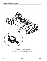
Страница 88: ...SECTION 3 CHASSIS TURNTABLE 3 46 JLG Lift 3121827 Figure 3 18 Battery Cable Connections...
Страница 90: ...SECTION 3 CHASSIS TURNTABLE 3 48 JLG Lift 3121827 Figure 3 20 On Board Generator...
Страница 97: ...SECTION 3 CHASSIS TURNTABLE 3121827 JLG Lift 3 55 Figure 3 22 Generator Components...
Страница 100: ...SECTION 3 CHASSIS TURNTABLE 3 58 JLG Lift 3121827 Figure 3 23 Generator System Analyzer Flow Chart...
Страница 116: ...SECTION 3 CHASSIS TURNTABLE 3 74 JLG Lift 3121827 NOTES...
Страница 125: ...SECTION 4 BOOM PLATFORM 3121827 JLG Lift 4 9 Figure 4 8 Jib Platform Components and Attaching Hardware...
Страница 127: ...SECTION 4 BOOM PLATFORM 3121827 JLG Lift 4 11 Figure 4 10 Boom Limit Switches...
Страница 140: ...SECTION 4 BOOM PLATFORM 4 24 JLG Lift 3121827 Figure 4 13 Rotator Counterbalance Valve...
Страница 178: ...SECTION 5 HYDRAULICS 5 24 JLG Lift 3121827 Figure 5 26 HydraForce Cartridge Torque Value Chart...
Страница 179: ...SECTION 5 HYDRAULICS 3121827 JLG Lift 5 25 Figure 5 27 Main Valve Components Prior to S N 62642...
Страница 214: ...SECTION 6 JLG CONTROL SYSTEM 6 34 JLG Lift 3121827 NOTES...
Страница 257: ......

