SECTION 3 - CHASSIS & TURNTABLE
3121827
– JLG Lift –
3-59
• Over Speed
If the engine speed exceeds the overspeed limit, the
engine will stop immediately and an overspeed alarm will
be indicated.
•
Underspeed
Enabled once TDBP (time delay bypass) period has
elapsed after engine startup. If the engine speed drops
below the underspeed limit, the engine will stop immedi-
ately and an engine underspeed alarm will be indicated.
•
Over crank
If the engine fails to start after a set number of start
attempts, the RBS will cease attempts to restart and an
engine over crank alarm will be indicated.
•
No Speed Signal
In the event of a loss of speed signal, the RBS will shut-
down and an engine no speed signal alarm will be indi-
cated. This shutdown is delayed by a factory set period to
ensure the fault was not momentary.
•
Over voltage
If the voltage measured at the alternator output exceeds
the high voltage setting, the RBS will stop immediately
and an RBS high output alarm will be indicated. This shut-
down is delayed by a factory set period to ensure the fault
was not caused by a transient condition. This feature pro-
tects the batteries and load from high DC voltages.
•
Engine Starting System Fault
Indicates a problem with either the engine start battery,
engine magneto, or magneto voltage regulator.
• Loss Of Voltage Sense
If the voltage measured at the alternator output is less
than half of the system nominal voltage, the RBS will stop
immediately and an RBS loss of voltage sense alarm will
be indicated. This feature protects the batteries and load
from high DC voltages due to a loss of output control.
•
Run Inhibited
The RBS unit is disabled by the run inhibited input.
Output Current and Voltage Settings
• Normal/Extended Output Voltage
The normal/extended output voltage setting is the voltage
at which the alternator changes under normal operating
conditions.
• Current Limit
The current limit setting determines the maximum alterna-
tor output current.
• High Voltage Shutdown Level
This setting determines the alternator output voltage at
which the high voltage shutdown occurs. This protects the
load from abnormally high voltages.
•
Finish Charging Current
The finish charging current determines the level of the cur-
rent alternator output must drop below for a low battery
voltage CTS to be removed. This ensures that the batter-
ies have accepted sufficient charge prior to shutting down
the RBS. This level is used along with the low battery volt-
age remove CTS level to determine when the RBS
removes the CTS after a low battery voltage CTS. If the
charging current falls below the finish charging current
while another CTS is active, the RBS will continue to oper-
ate at the normal/extended output voltage until all CTS’s
are removed.
Содержание JLG E400AJP
Страница 2: ......
Страница 21: ...SECTION 1 SPECIFICATIONS 3121827 JLG Lift 1 7 Figure 1 2 Operator Maintenance Lubrication Diagram...
Страница 32: ...SECTION 1 SPECIFICATIONS 1 18 JLG Lift 3121827 NOTES...
Страница 42: ...SECTION 2 GENERAL 2 10 JLG Lift 3121827 NOTES...
Страница 54: ...SECTION 3 CHASSIS TURNTABLE 3 12 JLG Lift 3121827 Figure 3 3 Speed Sensor Orientation...
Страница 55: ...SECTION 3 CHASSIS TURNTABLE 3121827 JLG Lift 3 13 Figure 3 4 Frame Mounted Electrical Components Sheet 1 of 2...
Страница 56: ...SECTION 3 CHASSIS TURNTABLE 3 14 JLG Lift 3121827 Figure 3 5 Frame Mounted Electrical Components Sheet 2 of 2...
Страница 60: ...SECTION 3 CHASSIS TURNTABLE 3 18 JLG Lift 3121827 Figure 3 7 Steering Components and Spindles...
Страница 62: ...SECTION 3 CHASSIS TURNTABLE 3 20 JLG Lift 3121827 Figure 3 9 Tilt Sensor Location...
Страница 86: ...SECTION 3 CHASSIS TURNTABLE 3 44 JLG Lift 3121827 Figure 3 16 Swing Components...
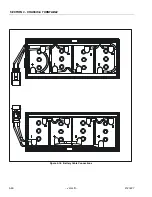
Страница 88: ...SECTION 3 CHASSIS TURNTABLE 3 46 JLG Lift 3121827 Figure 3 18 Battery Cable Connections...
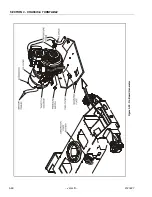
Страница 90: ...SECTION 3 CHASSIS TURNTABLE 3 48 JLG Lift 3121827 Figure 3 20 On Board Generator...
Страница 97: ...SECTION 3 CHASSIS TURNTABLE 3121827 JLG Lift 3 55 Figure 3 22 Generator Components...
Страница 100: ...SECTION 3 CHASSIS TURNTABLE 3 58 JLG Lift 3121827 Figure 3 23 Generator System Analyzer Flow Chart...
Страница 116: ...SECTION 3 CHASSIS TURNTABLE 3 74 JLG Lift 3121827 NOTES...
Страница 125: ...SECTION 4 BOOM PLATFORM 3121827 JLG Lift 4 9 Figure 4 8 Jib Platform Components and Attaching Hardware...
Страница 127: ...SECTION 4 BOOM PLATFORM 3121827 JLG Lift 4 11 Figure 4 10 Boom Limit Switches...
Страница 140: ...SECTION 4 BOOM PLATFORM 4 24 JLG Lift 3121827 Figure 4 13 Rotator Counterbalance Valve...
Страница 178: ...SECTION 5 HYDRAULICS 5 24 JLG Lift 3121827 Figure 5 26 HydraForce Cartridge Torque Value Chart...
Страница 179: ...SECTION 5 HYDRAULICS 3121827 JLG Lift 5 25 Figure 5 27 Main Valve Components Prior to S N 62642...
Страница 214: ...SECTION 6 JLG CONTROL SYSTEM 6 34 JLG Lift 3121827 NOTES...
Страница 257: ......

