SECTION 6 - JLG CONTROL SYSTEM
6-22
– JLG Lift –
3121827
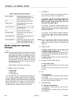
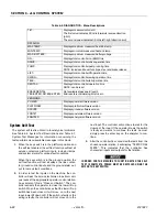
System Self Test
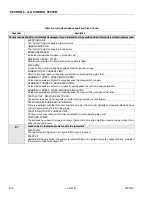
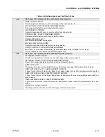
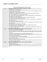
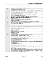
The system self test is utilized to locate typical problems.
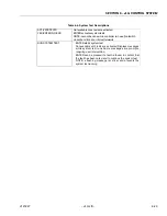
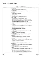
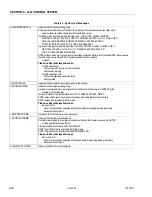
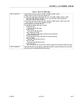
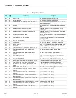
See Table 6-6, System Test Descriptions and Table 6-7,
System Test Messages for information concerning the
tests performed and available messages in this mode.
1.
When the keys witch is in the platform position and
the self test enabled, the self test function will test all
valves, contactors, platform inputs, indicator lamps,
and system alarms for various fault conditions.
When the keys witch is in the ground position, the
self test function will test all valves, the line contac-
tor, ground control inputs, and the ground alarm out-
put for various fault conditions.
2.
In order to test the inputs on the machine, the con-
troller will ask the service technician to perform vari-
ous tasks at the appropriate operator control station.
An example of this is “Close LLU Switch”. The con-
troller expects the operator to close the lower lift up
switch. When the controller sees that the lower lift up
switch has been closed, it will move on to the next
input, lower lift down LLD. If the switch is faulty or the
wiring is faulty, the controller will not move on to the
next input. The controller will continue to wait for the
closure of the input. If the operator knows the switch
is faulty and wants to continue the tests he must
simply press the enter key on the analyzer to con-
tinue.
3.
After the controller has conducted the tests from the
chosen operator station, it will display “TESTS COM-
PLETE”. This indicates that the controller has
checked all inputs and outputs for that station.
IN ORDER FOR THE MACHINE TO FUNCTION AFTER THE SELF
TEST IS COMPLETE, POWER MUST BE RECYCLED USING THE
EMS OR THE KEY SWITCH.
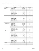
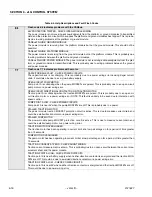
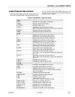
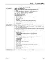
TILT...
Displays measured vehicle tilt
The first value indicates tilt in die forwards reverse direction
(pitch)
The second value indicates tilt in the left/ right direction (roll)
DATALOG
MAX.TEMP...
Displays maximum measured heat sink temp.
MIN.TEMP...
Displays minimum measured heat sink temp.
MAX. BATTERY..
Displays maximum measured battery voltage
ON...
Displays total controller on (EMS) time
DRIVE...
Displays total controller drive operation time
PUMP...
Displays total controller pump running time
NOTE: includes all boom functions, steer and brake release
LIFT..
Displays total controller lift operation time
SWING...
Displays total controller swing operation time
TELE...
Displays total controller tell operation time
RENTAL...
Displays total controller operation time
NOTE: can be reset
ERASE RENTAL
YES:ENTER, NO:ESC ENTER
Not available at password level 2
Enter
resets rental datalog time to zero
VERSIONS
POWER
Displays power software version
PLATFORM
Displays platform software version
GROUND
Displays ground software version
POSITILT
Displays postulate software version
ANALYZER
Displays analyzer software version
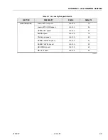
Table 6-5. DIAGNOSTICS - Menu Descriptions
Содержание JLG E400AJP
Страница 2: ......
Страница 21: ...SECTION 1 SPECIFICATIONS 3121827 JLG Lift 1 7 Figure 1 2 Operator Maintenance Lubrication Diagram...
Страница 32: ...SECTION 1 SPECIFICATIONS 1 18 JLG Lift 3121827 NOTES...
Страница 42: ...SECTION 2 GENERAL 2 10 JLG Lift 3121827 NOTES...
Страница 54: ...SECTION 3 CHASSIS TURNTABLE 3 12 JLG Lift 3121827 Figure 3 3 Speed Sensor Orientation...
Страница 55: ...SECTION 3 CHASSIS TURNTABLE 3121827 JLG Lift 3 13 Figure 3 4 Frame Mounted Electrical Components Sheet 1 of 2...
Страница 56: ...SECTION 3 CHASSIS TURNTABLE 3 14 JLG Lift 3121827 Figure 3 5 Frame Mounted Electrical Components Sheet 2 of 2...
Страница 60: ...SECTION 3 CHASSIS TURNTABLE 3 18 JLG Lift 3121827 Figure 3 7 Steering Components and Spindles...
Страница 62: ...SECTION 3 CHASSIS TURNTABLE 3 20 JLG Lift 3121827 Figure 3 9 Tilt Sensor Location...
Страница 86: ...SECTION 3 CHASSIS TURNTABLE 3 44 JLG Lift 3121827 Figure 3 16 Swing Components...
Страница 88: ...SECTION 3 CHASSIS TURNTABLE 3 46 JLG Lift 3121827 Figure 3 18 Battery Cable Connections...
Страница 90: ...SECTION 3 CHASSIS TURNTABLE 3 48 JLG Lift 3121827 Figure 3 20 On Board Generator...
Страница 97: ...SECTION 3 CHASSIS TURNTABLE 3121827 JLG Lift 3 55 Figure 3 22 Generator Components...
Страница 100: ...SECTION 3 CHASSIS TURNTABLE 3 58 JLG Lift 3121827 Figure 3 23 Generator System Analyzer Flow Chart...
Страница 116: ...SECTION 3 CHASSIS TURNTABLE 3 74 JLG Lift 3121827 NOTES...
Страница 125: ...SECTION 4 BOOM PLATFORM 3121827 JLG Lift 4 9 Figure 4 8 Jib Platform Components and Attaching Hardware...
Страница 127: ...SECTION 4 BOOM PLATFORM 3121827 JLG Lift 4 11 Figure 4 10 Boom Limit Switches...
Страница 140: ...SECTION 4 BOOM PLATFORM 4 24 JLG Lift 3121827 Figure 4 13 Rotator Counterbalance Valve...
Страница 178: ...SECTION 5 HYDRAULICS 5 24 JLG Lift 3121827 Figure 5 26 HydraForce Cartridge Torque Value Chart...
Страница 179: ...SECTION 5 HYDRAULICS 3121827 JLG Lift 5 25 Figure 5 27 Main Valve Components Prior to S N 62642...
Страница 214: ...SECTION 6 JLG CONTROL SYSTEM 6 34 JLG Lift 3121827 NOTES...
Страница 257: ......

