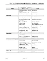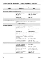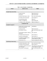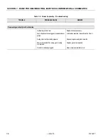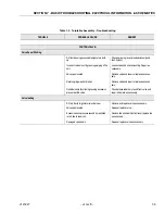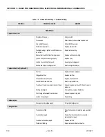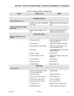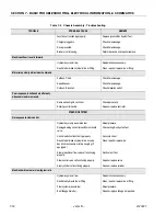
SECTION 6 - JLG CONTROL SYSTEM
6-32
– JLG Lift –
3121827
776
77
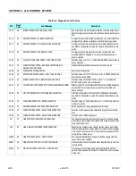
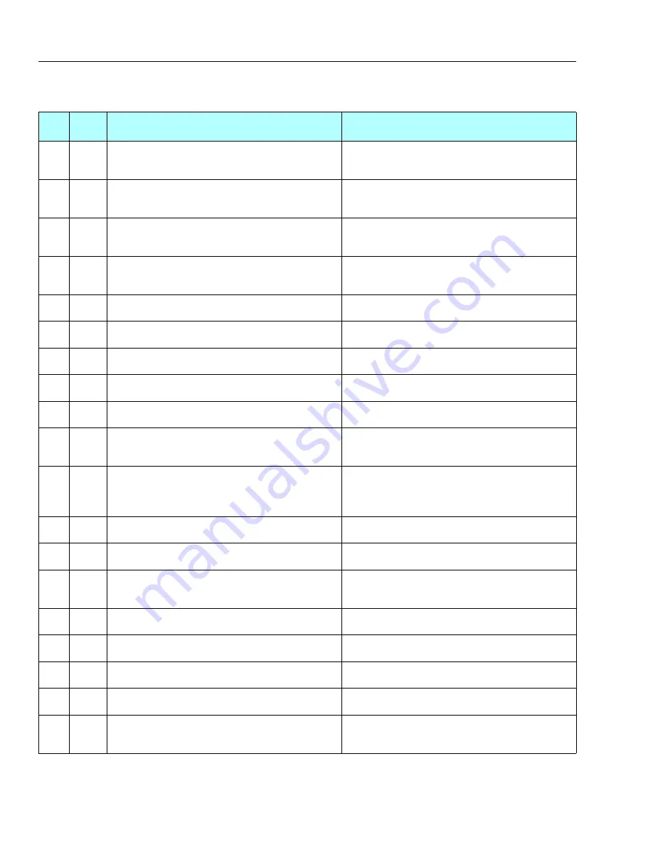
STALLED PUMP MOTOR OR POWER WIRING ERROR
The power module pump MOSFET protection circuit is active,
This is due to a massive current drain and could be a stalled pump
motor or a power wiring error
777
77
OPEN CIRCUIT PUMP MOTOR WIRING
Pump point A is collapsing when the pump MOSFETs are pulsed,
this maybe due to an OPEN circuit pump motor or a power wiring
error
7734
77
TRACTION A HIGH - CHECK POWER CIRCUITS
Traction point A is near battery supply when neither direction con-
tactor is energized and the traction MOSFETs are OFF, this maybe
due to a welded direction contactor or a power wiring error
7735
77
TRACTION A LOW - CHECK POWER CIRCUITS
Traction point A is near ZERO volts when neither direction contac-
tor is energized and the traction MOSFETs are OFF, this maybe due
to a power wiring error
7736
77
TRACTION MOTOR OVERLOADED
The traction motor has been operating in current limit at a low per-
centage on for a long time greater than 10 seconds
7737
77
PUMP MOTOR OVERLOADED
The pump motor has been operating in current limit at a low per-
centage on for a long time greater than 10 seconds
7738
77
PUMP A LOW - CHECK POWER CIRCUITS
Pump point A is near ZERO volts when the pump MOSFETs are
OFF, this maybe due to a power wiring error
7739
77
B+ AND A CROSSED - CHECK POWER CIRCUITS
startup test detected B+ is connected to point A and point A is
connected to B+
7740
77
TRACTION CURRENT AT ZERO - CHECK SHUNT WIRING
Traction current is at ZERO, this maybe due to an open circuit
between the current measurement shunt and the power module
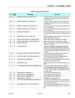
826
82
RUNNING AT CREEP - PLATFORM OVERLOADED
All functions at creep, the Load Sensing System indicates the
Platform is overloaded AND is configured to warn only while the
Platform is overloaded.
827
82
DRIVE & BOOM PREVENTED - PLATFORM OVERLOADED
Driving and boom functions are not possible while the Load Sens-
ing System indicates the Platform is overloaded AND is config-
ured to prevent drive and boom functions while the Platform is
overloaded.
99125
99
POWER MODULE FAILURE - HWFS CODE 2
Hardware failsafe tests did not com plete because traction point A
is not safe, or the hardware failsafe is permanently tripped
99126
99
POWER MODULE FAILURE - HWFS CODE 3
Hardware failsafe tests did not complete because a contactor
was energized when all should be turned off
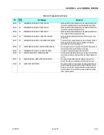
99127
99
POWER MODULE FAILURE - HWFS CODE 4
Hardware failsafe tests did not complete because the hardware
failsafe tripped immediately when the traction MOSFETs were
turned ON
99128
99
POWER MODULE FAILURE - HWFS CODE 10
Hardware failsafe tests failed because the hardware failsafe did
not trip within the allowed test time
99129
99
POWER MODULE FAILURE - HWFS CODE 11
Hardware failsafe tests failed because the hardware failsafe
tripped too slowly
99130
99
POWER MODULE FAILURE - HWFS CODE 12
Hardware failsafe tests failed because the hardware failsafe
tripped too Quickly
99131
99
POWER MODULE FAILURE - HWFS CODE 13
Hardware failsafe tests failed because the hardware failsafe
remained tripped when the traction MOSFETs were turned OFF
99132
99
POWER MODULE FAILURE - HWFS CODE 14
Hardware failsafe tests failed because the hardware failsafe the
line contactor could not be energized when the hardware failsafe
was tripped
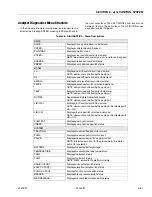
Table 6-8. Diagnostic Fault Codes
DTC
Flash
Code
Fault Message
Description
Содержание JLG E400AJP
Страница 2: ......
Страница 21: ...SECTION 1 SPECIFICATIONS 3121827 JLG Lift 1 7 Figure 1 2 Operator Maintenance Lubrication Diagram...
Страница 32: ...SECTION 1 SPECIFICATIONS 1 18 JLG Lift 3121827 NOTES...
Страница 42: ...SECTION 2 GENERAL 2 10 JLG Lift 3121827 NOTES...
Страница 54: ...SECTION 3 CHASSIS TURNTABLE 3 12 JLG Lift 3121827 Figure 3 3 Speed Sensor Orientation...
Страница 55: ...SECTION 3 CHASSIS TURNTABLE 3121827 JLG Lift 3 13 Figure 3 4 Frame Mounted Electrical Components Sheet 1 of 2...
Страница 56: ...SECTION 3 CHASSIS TURNTABLE 3 14 JLG Lift 3121827 Figure 3 5 Frame Mounted Electrical Components Sheet 2 of 2...
Страница 60: ...SECTION 3 CHASSIS TURNTABLE 3 18 JLG Lift 3121827 Figure 3 7 Steering Components and Spindles...
Страница 62: ...SECTION 3 CHASSIS TURNTABLE 3 20 JLG Lift 3121827 Figure 3 9 Tilt Sensor Location...
Страница 86: ...SECTION 3 CHASSIS TURNTABLE 3 44 JLG Lift 3121827 Figure 3 16 Swing Components...
Страница 88: ...SECTION 3 CHASSIS TURNTABLE 3 46 JLG Lift 3121827 Figure 3 18 Battery Cable Connections...
Страница 90: ...SECTION 3 CHASSIS TURNTABLE 3 48 JLG Lift 3121827 Figure 3 20 On Board Generator...
Страница 97: ...SECTION 3 CHASSIS TURNTABLE 3121827 JLG Lift 3 55 Figure 3 22 Generator Components...
Страница 100: ...SECTION 3 CHASSIS TURNTABLE 3 58 JLG Lift 3121827 Figure 3 23 Generator System Analyzer Flow Chart...
Страница 116: ...SECTION 3 CHASSIS TURNTABLE 3 74 JLG Lift 3121827 NOTES...
Страница 125: ...SECTION 4 BOOM PLATFORM 3121827 JLG Lift 4 9 Figure 4 8 Jib Platform Components and Attaching Hardware...
Страница 127: ...SECTION 4 BOOM PLATFORM 3121827 JLG Lift 4 11 Figure 4 10 Boom Limit Switches...
Страница 140: ...SECTION 4 BOOM PLATFORM 4 24 JLG Lift 3121827 Figure 4 13 Rotator Counterbalance Valve...
Страница 178: ...SECTION 5 HYDRAULICS 5 24 JLG Lift 3121827 Figure 5 26 HydraForce Cartridge Torque Value Chart...
Страница 179: ...SECTION 5 HYDRAULICS 3121827 JLG Lift 5 25 Figure 5 27 Main Valve Components Prior to S N 62642...
Страница 214: ...SECTION 6 JLG CONTROL SYSTEM 6 34 JLG Lift 3121827 NOTES...
Страница 257: ......

