SECTION 3 - CHASSIS & TURNTABLE
3121827
– JLG Lift –
3-39
3.8 SWING BEARING
Turntable Bearing Mounting Bolt Condition
Check
NOTE:
This check is designed to replace the existing bear-
ing bolt torque checks on JLG Lifts in service. This
check must be performed after the first 50 hours of
machine operation and every 600 hours of machine
operation thereafter. If during this check any bolts
are found to be missing or loose, replace missing or
loose bolts with new bolts and torque to the value
specified in the torque chart, after lubricating the bolt
threads with loctite #271. After replacing and
retorquing bolt or bolts recheck all existing bolts for
looseness.
1.
Check the frame to bearing attach bolts as follows:
a.
Elevate the fully retracted boom to 70 degrees
(full elevation).
b.
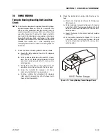
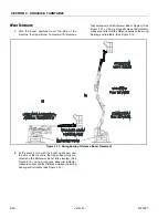
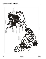
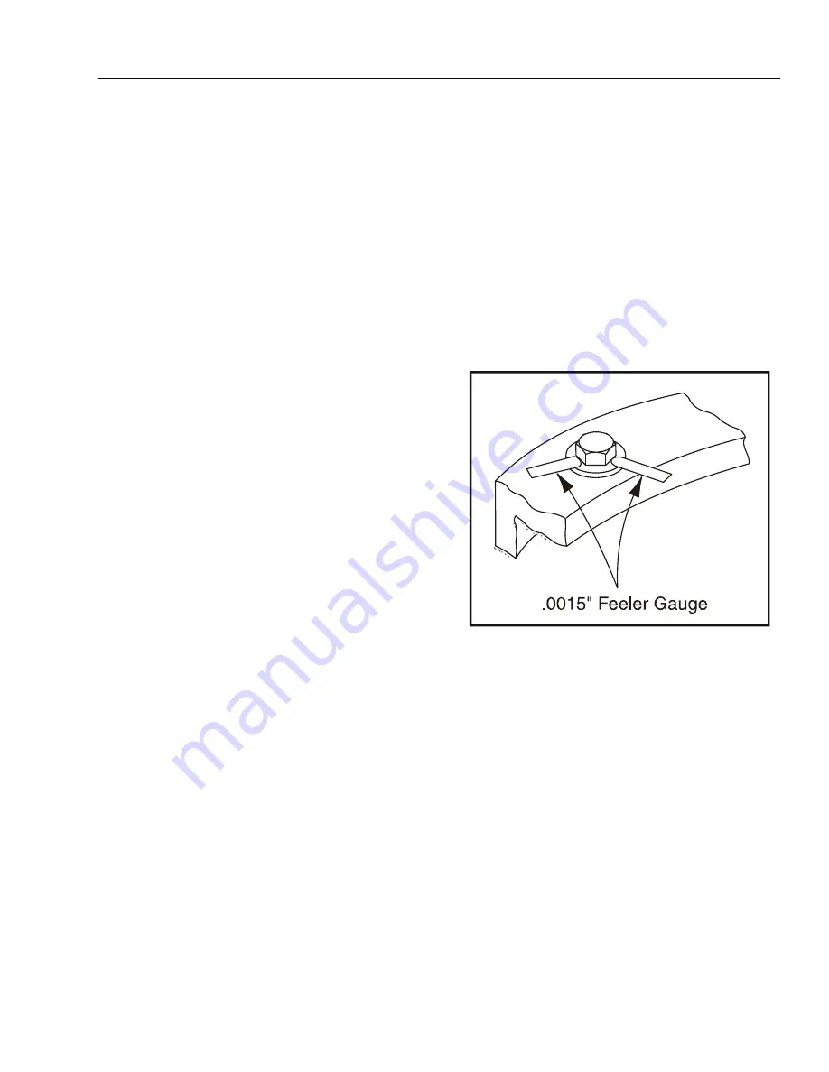
At the positions indicated on Figure 3-12. try and
insert the 0.0015” feeler gauge between the bolt
head and hardened washer at the arrow indi-
cated position.
c.
Assure that the 0.0015" feeler gauge will not
penetrate under the bolt head to the bolt shank.
d.
Swing the turntable 90 degrees, and check
some selected bolts at the new position.
e.
Continue rotating the turntable at 90 degrees
intervals until a sampling of bolts have been
checked in all quadrants.
2.
Check the turntable to bearing attach bolts as fol-
lows:
a.
Elevate the fully retracted boom to 70 degrees
(full elevation).
b.
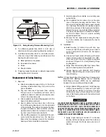
At the positions indicated on Figure 3-13. try and
insert the 0.0015" feeler gauge between the bolt
head and hardened washer at the arrow indi-
cated position.
c.
Lower the boom to horizontal and fully extend
the boom.
d.
At the position indicated on Figure 3-12. try and
insert the 0.0015” feeler gauge between the bolt
head and hardened washer at the arrow indi-
cated position.
Figure 3-12. Swing Bearing Feeler Gauge Check
Содержание JLG E400AJP
Страница 2: ......
Страница 21: ...SECTION 1 SPECIFICATIONS 3121827 JLG Lift 1 7 Figure 1 2 Operator Maintenance Lubrication Diagram...
Страница 32: ...SECTION 1 SPECIFICATIONS 1 18 JLG Lift 3121827 NOTES...
Страница 42: ...SECTION 2 GENERAL 2 10 JLG Lift 3121827 NOTES...
Страница 54: ...SECTION 3 CHASSIS TURNTABLE 3 12 JLG Lift 3121827 Figure 3 3 Speed Sensor Orientation...
Страница 55: ...SECTION 3 CHASSIS TURNTABLE 3121827 JLG Lift 3 13 Figure 3 4 Frame Mounted Electrical Components Sheet 1 of 2...
Страница 56: ...SECTION 3 CHASSIS TURNTABLE 3 14 JLG Lift 3121827 Figure 3 5 Frame Mounted Electrical Components Sheet 2 of 2...
Страница 60: ...SECTION 3 CHASSIS TURNTABLE 3 18 JLG Lift 3121827 Figure 3 7 Steering Components and Spindles...
Страница 62: ...SECTION 3 CHASSIS TURNTABLE 3 20 JLG Lift 3121827 Figure 3 9 Tilt Sensor Location...
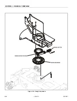
Страница 86: ...SECTION 3 CHASSIS TURNTABLE 3 44 JLG Lift 3121827 Figure 3 16 Swing Components...
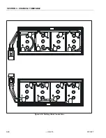
Страница 88: ...SECTION 3 CHASSIS TURNTABLE 3 46 JLG Lift 3121827 Figure 3 18 Battery Cable Connections...
Страница 90: ...SECTION 3 CHASSIS TURNTABLE 3 48 JLG Lift 3121827 Figure 3 20 On Board Generator...
Страница 97: ...SECTION 3 CHASSIS TURNTABLE 3121827 JLG Lift 3 55 Figure 3 22 Generator Components...
Страница 100: ...SECTION 3 CHASSIS TURNTABLE 3 58 JLG Lift 3121827 Figure 3 23 Generator System Analyzer Flow Chart...
Страница 116: ...SECTION 3 CHASSIS TURNTABLE 3 74 JLG Lift 3121827 NOTES...
Страница 125: ...SECTION 4 BOOM PLATFORM 3121827 JLG Lift 4 9 Figure 4 8 Jib Platform Components and Attaching Hardware...
Страница 127: ...SECTION 4 BOOM PLATFORM 3121827 JLG Lift 4 11 Figure 4 10 Boom Limit Switches...
Страница 140: ...SECTION 4 BOOM PLATFORM 4 24 JLG Lift 3121827 Figure 4 13 Rotator Counterbalance Valve...
Страница 178: ...SECTION 5 HYDRAULICS 5 24 JLG Lift 3121827 Figure 5 26 HydraForce Cartridge Torque Value Chart...
Страница 179: ...SECTION 5 HYDRAULICS 3121827 JLG Lift 5 25 Figure 5 27 Main Valve Components Prior to S N 62642...
Страница 214: ...SECTION 6 JLG CONTROL SYSTEM 6 34 JLG Lift 3121827 NOTES...
Страница 257: ......


