SECTION 3 - CHASSIS & TURNTABLE
3-2
– JLG Lift –
3121827
2.
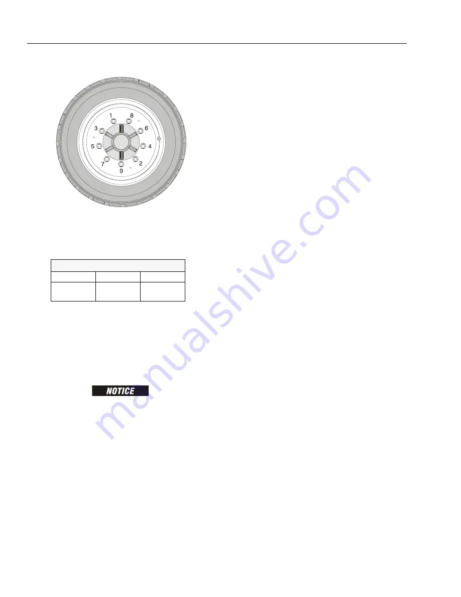
Tighten nuts in the following sequence:
3.
The tightening of the nuts should be done in stages.
Following the recommended sequence, tighten nuts
per wheel torque chart.
4.
Wheel nuts should be torqued after first 50 hours of
operation and after each wheel removal. Check
torque every 3 months or 150 hours of operation.
3.2 SPINDLE
Setting Wheel Bearing End Play
BE SURE NOT TO OVER-TIGHTEN THE SPINDLE NUT.
1.
Tighten the spindle nut to assure the bearings are
properly seated.
2.
Loosen the spindle nut completely until the nut can
be turned by hand.
3.
Tighten the spindle nut by hand using a socket with-
out rotating the hub.
4.
If the cotter pin can be assembled with the spindle
nut finger tight, insert cotter pin without backing the
nut off. If the cotter pin cannot be assembled with
the spindle nut hand tight, tighten the spindle nut to
the nearest available slot and insert cotter pin. If
more than ½ of the cotter pin hole in the spindle can
be seen in a slot, back nut off to nearest slot and
insert pin.
5.
Check the unit for end play by moving the hub up &
down parallel along the centerline of the spindle. If
you can feel excessive end play (over the 0.010"
[0.25 mm] specification), recheck the nut to see
what is causing the excessive end play. Keep in
mind that there can be some movement and still be
within the 0.010" (0.25 mm) maximum specification.
If there is no way of getting the excessive end play
out by using your fingers, a socket or wrench may
have to be used to set the end play.
6.
The units should be checked visually to make sure
the cotter pins are installed and that the correct
components have been used. Each unit must also
be checked for the proper feel to make sure there
isn’t excessive end play and the hubs turn freely.
7.
Insert the dust cap and check to make sure the cot-
ter pin is not going to interfere. Cap must be pressed
all the way down. The unit should be checked again
to assure it spins freely after the dust cap is installed.
Specifications
The end play specification is 0.001”/0.010" (0.025 / 0.254
mm) for all units.
Checking
The end play is checked by clamping the spindle in a fix-
ture or vise and moving the hub parallel to the spindle
centerline without rocking the hub. If the end play is set
properly the following should apply:
1.
Hub should rotate freely when spun by hand.
2.
The hub should not be noticeably loose when
moved parallel with spindle centerline.
Greasing Requirements
Hub assemblies shall have grease packed in the bearings
via an appropriate greasing spindle or by hand. In either
method, the bearing must be greased so the grease is
forced thru the entire bearing cavity and thru the rollers of
both inner and outer bearings.
Dust or grease caps used shall have grease applied to the
inside of the cap.
The bearing cavity shall be filled 50 - 80% full of grease on
all applications.
Dust or grease caps shall also be filled 10-20% full of
grease on all applications prior to final assembly.
Visually verify that grease has flowed thru all rollers of the
inner and outer bearings.
Table 3-1. Wheel Torque Chart
TORQUE SEQUENCE
1st Stage
2nd Stage
3rd Stage
40 ft. lbs.
(55 Nm)
100 ft. lbs.
(130 Nm)
170 ft. lbs.
(255 Nm)
Содержание JLG E400AJP
Страница 2: ......
Страница 21: ...SECTION 1 SPECIFICATIONS 3121827 JLG Lift 1 7 Figure 1 2 Operator Maintenance Lubrication Diagram...
Страница 32: ...SECTION 1 SPECIFICATIONS 1 18 JLG Lift 3121827 NOTES...
Страница 42: ...SECTION 2 GENERAL 2 10 JLG Lift 3121827 NOTES...
Страница 54: ...SECTION 3 CHASSIS TURNTABLE 3 12 JLG Lift 3121827 Figure 3 3 Speed Sensor Orientation...
Страница 55: ...SECTION 3 CHASSIS TURNTABLE 3121827 JLG Lift 3 13 Figure 3 4 Frame Mounted Electrical Components Sheet 1 of 2...
Страница 56: ...SECTION 3 CHASSIS TURNTABLE 3 14 JLG Lift 3121827 Figure 3 5 Frame Mounted Electrical Components Sheet 2 of 2...
Страница 60: ...SECTION 3 CHASSIS TURNTABLE 3 18 JLG Lift 3121827 Figure 3 7 Steering Components and Spindles...
Страница 62: ...SECTION 3 CHASSIS TURNTABLE 3 20 JLG Lift 3121827 Figure 3 9 Tilt Sensor Location...
Страница 86: ...SECTION 3 CHASSIS TURNTABLE 3 44 JLG Lift 3121827 Figure 3 16 Swing Components...
Страница 88: ...SECTION 3 CHASSIS TURNTABLE 3 46 JLG Lift 3121827 Figure 3 18 Battery Cable Connections...
Страница 90: ...SECTION 3 CHASSIS TURNTABLE 3 48 JLG Lift 3121827 Figure 3 20 On Board Generator...
Страница 97: ...SECTION 3 CHASSIS TURNTABLE 3121827 JLG Lift 3 55 Figure 3 22 Generator Components...
Страница 100: ...SECTION 3 CHASSIS TURNTABLE 3 58 JLG Lift 3121827 Figure 3 23 Generator System Analyzer Flow Chart...
Страница 116: ...SECTION 3 CHASSIS TURNTABLE 3 74 JLG Lift 3121827 NOTES...
Страница 125: ...SECTION 4 BOOM PLATFORM 3121827 JLG Lift 4 9 Figure 4 8 Jib Platform Components and Attaching Hardware...
Страница 127: ...SECTION 4 BOOM PLATFORM 3121827 JLG Lift 4 11 Figure 4 10 Boom Limit Switches...
Страница 140: ...SECTION 4 BOOM PLATFORM 4 24 JLG Lift 3121827 Figure 4 13 Rotator Counterbalance Valve...
Страница 178: ...SECTION 5 HYDRAULICS 5 24 JLG Lift 3121827 Figure 5 26 HydraForce Cartridge Torque Value Chart...
Страница 179: ...SECTION 5 HYDRAULICS 3121827 JLG Lift 5 25 Figure 5 27 Main Valve Components Prior to S N 62642...
Страница 214: ...SECTION 6 JLG CONTROL SYSTEM 6 34 JLG Lift 3121827 NOTES...
Страница 257: ......

