SECTION 4 - BOOM & PLATFORM
3121827
– JLG Lift –
4-15
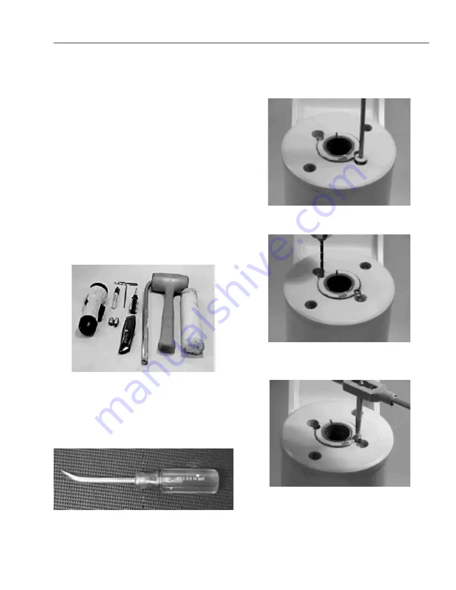
Tools Required for Assembly/Disassembly
Upon assembly and disassembly of the actuator there are
basic tools required. The tools and their intended func-
tions are as follows:
1.
Flashlight- helps examine timing marks, component
failure and overall condition.
2.
Felt Marker- match mark the timing marks and out-
line troubled areas.
3.
Allen wrench- removal of port plugs and setscrews.
4.
Box knife- removal of seals.
5.
Seal tool- assembly and disassembly of seals and
wear guides.
6.
Pry bar- removal of end cap and manual rotation of
shaft.
7.
Rubber mallet- removal and installation of shaft and
piston sleeve assembly.
8.
Nylon drift- installation of piston sleeve.
9.
End cap dowel pins- removal and installation of end
cap (sold with Helac seal kit).
The seal tool is merely a customized standard flat head-
screwdriver. To make this tool you will need to heat the flat
end with a torch. Secure the heated end of the screwdriver
in a vice and physically bend the heated end to a slight
radius. Once the radius is achieved round off all sharp
edges of the heated end by using a grinder. There may be
some slight modifications for your own personal prefer-
ence.
Disassembly
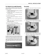
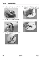
1.
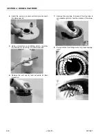
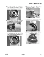
Remove the cap screws (113) over end cap lock
pins (109).
2.
Using a 1/8” (3.18mm) drill bit, drill a hole in the cen-
ter of each lock pin to a depth of approximately 3/
16” (4.76mm).
3.
Remove the lock pins using an “Easy Out” (a size
#2 is shown). If the pin will not come out with the
“Easy Out”, use 5/16” drill bit to a depth of 1/2”
(12.7mm)todrill out the entire pin.
Содержание JLG E400AJP
Страница 2: ......
Страница 21: ...SECTION 1 SPECIFICATIONS 3121827 JLG Lift 1 7 Figure 1 2 Operator Maintenance Lubrication Diagram...
Страница 32: ...SECTION 1 SPECIFICATIONS 1 18 JLG Lift 3121827 NOTES...
Страница 42: ...SECTION 2 GENERAL 2 10 JLG Lift 3121827 NOTES...
Страница 54: ...SECTION 3 CHASSIS TURNTABLE 3 12 JLG Lift 3121827 Figure 3 3 Speed Sensor Orientation...
Страница 55: ...SECTION 3 CHASSIS TURNTABLE 3121827 JLG Lift 3 13 Figure 3 4 Frame Mounted Electrical Components Sheet 1 of 2...
Страница 56: ...SECTION 3 CHASSIS TURNTABLE 3 14 JLG Lift 3121827 Figure 3 5 Frame Mounted Electrical Components Sheet 2 of 2...
Страница 60: ...SECTION 3 CHASSIS TURNTABLE 3 18 JLG Lift 3121827 Figure 3 7 Steering Components and Spindles...
Страница 62: ...SECTION 3 CHASSIS TURNTABLE 3 20 JLG Lift 3121827 Figure 3 9 Tilt Sensor Location...
Страница 86: ...SECTION 3 CHASSIS TURNTABLE 3 44 JLG Lift 3121827 Figure 3 16 Swing Components...
Страница 88: ...SECTION 3 CHASSIS TURNTABLE 3 46 JLG Lift 3121827 Figure 3 18 Battery Cable Connections...
Страница 90: ...SECTION 3 CHASSIS TURNTABLE 3 48 JLG Lift 3121827 Figure 3 20 On Board Generator...
Страница 97: ...SECTION 3 CHASSIS TURNTABLE 3121827 JLG Lift 3 55 Figure 3 22 Generator Components...
Страница 100: ...SECTION 3 CHASSIS TURNTABLE 3 58 JLG Lift 3121827 Figure 3 23 Generator System Analyzer Flow Chart...
Страница 116: ...SECTION 3 CHASSIS TURNTABLE 3 74 JLG Lift 3121827 NOTES...
Страница 125: ...SECTION 4 BOOM PLATFORM 3121827 JLG Lift 4 9 Figure 4 8 Jib Platform Components and Attaching Hardware...
Страница 127: ...SECTION 4 BOOM PLATFORM 3121827 JLG Lift 4 11 Figure 4 10 Boom Limit Switches...
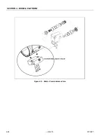
Страница 140: ...SECTION 4 BOOM PLATFORM 4 24 JLG Lift 3121827 Figure 4 13 Rotator Counterbalance Valve...
Страница 178: ...SECTION 5 HYDRAULICS 5 24 JLG Lift 3121827 Figure 5 26 HydraForce Cartridge Torque Value Chart...
Страница 179: ...SECTION 5 HYDRAULICS 3121827 JLG Lift 5 25 Figure 5 27 Main Valve Components Prior to S N 62642...
Страница 214: ...SECTION 6 JLG CONTROL SYSTEM 6 34 JLG Lift 3121827 NOTES...
Страница 257: ......


