SECTION 6 - JLG CONTROL SYSTEM
3121827
– JLG Lift –
6-17
9/9
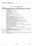
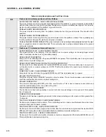
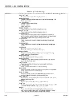
Flash code 9/9 indicates problems with the controller.
POWER MODULE FAILURE: CONTACTOR DRIVE CODE 1
A contactor remained energized when turned off.
POWER MODULE FAILURE: HWFS CODE 2
The hardware fail-safe tests did not complete because traction point A is not safe, or the hardware fail-safe
is permanently tripped.
POWER MODULE FAILURE: HWFS CODE 3
The hardware fail-safe tests did not complete because a contactor was energized when all should be turned
off
POWER MODULE FAILURE: HWFS CODE 4
The hardware fail-safe tests did not complete because the hardware fail-safe tripped immediately when the
traction MOSFETs were turned on.
POWER MODULE FAILURE: HWFS CODE 10
The hardware fail-safe tests failed because the hardware fail-safe did not trip within the allowed test time.
POWER MODULE FAILURE: HWFS CODE 11
The hardware fail-safe tests failed because the hardware fail-safe tripped too slowly.
POWER MODULE FAILURE: HWFS CODE 12
The hardware fail-safe tests failed because the hardware fail-safe tripped too quickly.
POWER MODULE FAILURE: HWFS CODE 13
The hardware fail-safe tests failed because the hardware fail-safe remained tripped when the traction MOS-
FETs were turned off.
POWER MODULE FAILURE: HWFS CODE 14
The hardware fail-safe tests failed because the line contactor could still be energized when the hardware
fail-safe was tripped
POWER MODULE FAILURE: HWFS CODE 15
The hardware fail-safe tests failed because the contactor drive fail-safe did not trip within the allowed test
time.
POWER MODULE FAILURE: HWFS CODE 16
The hardware fail-safe tests failed because the contactor drive fail-safe tripped too slowly.
POWER MODULE FAILURE: HWFS CODE 17
The hardware fail-safe tests failed because the contactor drive fail-safe tripped too quickly.
POWER MODULE FAILURE: HWFS TEST STALLED
The hardware fail-safe tests did not complete, but no reason can be determined.
POWER MODULE FAILURE: BAD TEMPERATURE SENSOR
The temperature sensor measurement is invalid, this is probably due to a disconnected wire within the
power module. The possibility of other disconnected wires (which could cause dangerous system function)
means that the controller is shut down.
POWER MODULE FAILURE: S/C LINE CONTACTOR DRIVER The line contactor energized when the foot-
switch was closed, before it was turned on, this is probably due to a failed driver within the power module,
although it could be due to bad power module wirings
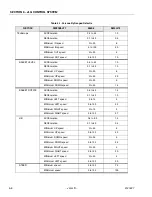
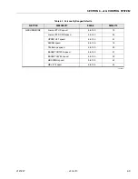
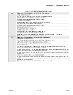
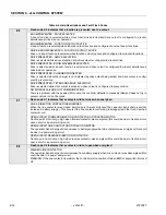
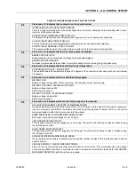
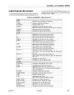
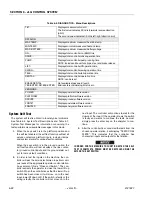
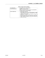
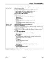
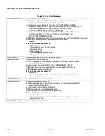
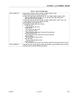
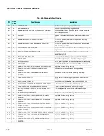
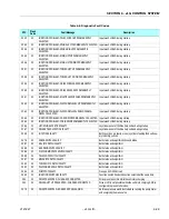
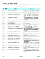
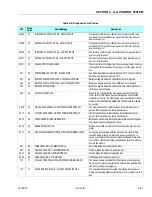
Table 6-4. Help Descriptions and Fault Flash Codes
Содержание JLG E400AJP
Страница 2: ......
Страница 21: ...SECTION 1 SPECIFICATIONS 3121827 JLG Lift 1 7 Figure 1 2 Operator Maintenance Lubrication Diagram...
Страница 32: ...SECTION 1 SPECIFICATIONS 1 18 JLG Lift 3121827 NOTES...
Страница 42: ...SECTION 2 GENERAL 2 10 JLG Lift 3121827 NOTES...
Страница 54: ...SECTION 3 CHASSIS TURNTABLE 3 12 JLG Lift 3121827 Figure 3 3 Speed Sensor Orientation...
Страница 55: ...SECTION 3 CHASSIS TURNTABLE 3121827 JLG Lift 3 13 Figure 3 4 Frame Mounted Electrical Components Sheet 1 of 2...
Страница 56: ...SECTION 3 CHASSIS TURNTABLE 3 14 JLG Lift 3121827 Figure 3 5 Frame Mounted Electrical Components Sheet 2 of 2...
Страница 60: ...SECTION 3 CHASSIS TURNTABLE 3 18 JLG Lift 3121827 Figure 3 7 Steering Components and Spindles...
Страница 62: ...SECTION 3 CHASSIS TURNTABLE 3 20 JLG Lift 3121827 Figure 3 9 Tilt Sensor Location...
Страница 86: ...SECTION 3 CHASSIS TURNTABLE 3 44 JLG Lift 3121827 Figure 3 16 Swing Components...
Страница 88: ...SECTION 3 CHASSIS TURNTABLE 3 46 JLG Lift 3121827 Figure 3 18 Battery Cable Connections...
Страница 90: ...SECTION 3 CHASSIS TURNTABLE 3 48 JLG Lift 3121827 Figure 3 20 On Board Generator...
Страница 97: ...SECTION 3 CHASSIS TURNTABLE 3121827 JLG Lift 3 55 Figure 3 22 Generator Components...
Страница 100: ...SECTION 3 CHASSIS TURNTABLE 3 58 JLG Lift 3121827 Figure 3 23 Generator System Analyzer Flow Chart...
Страница 116: ...SECTION 3 CHASSIS TURNTABLE 3 74 JLG Lift 3121827 NOTES...
Страница 125: ...SECTION 4 BOOM PLATFORM 3121827 JLG Lift 4 9 Figure 4 8 Jib Platform Components and Attaching Hardware...
Страница 127: ...SECTION 4 BOOM PLATFORM 3121827 JLG Lift 4 11 Figure 4 10 Boom Limit Switches...
Страница 140: ...SECTION 4 BOOM PLATFORM 4 24 JLG Lift 3121827 Figure 4 13 Rotator Counterbalance Valve...
Страница 178: ...SECTION 5 HYDRAULICS 5 24 JLG Lift 3121827 Figure 5 26 HydraForce Cartridge Torque Value Chart...
Страница 179: ...SECTION 5 HYDRAULICS 3121827 JLG Lift 5 25 Figure 5 27 Main Valve Components Prior to S N 62642...
Страница 214: ...SECTION 6 JLG CONTROL SYSTEM 6 34 JLG Lift 3121827 NOTES...
Страница 257: ......

