SECTION 3 - CHASSIS & TURNTABLE
3121827
– JLG Lift –
3-67
Warnings and Safety Precautions
THE RBS MAY START WITHOUT WARNING.
MORE THAN ONE LIVE CIRCUIT IS USED INSIDE THE RBS CON-
TROL PANEL. EXERCISE CAUTION WHEN THE CONTROL PANEL
IS OPEN, EVEN WHEN THE RBS IS NOT RUNNING.
System Controls
INHIBIT RUN INPUT
The inhibit run input prevents the RBS from starting, clears
any existing calls to start and stops the engine immedi-
ately. To return to normal operating mode, the inhibit run
input must be removed.
MANUAL CALL TO START
The manual call to start input initiates an automatic run of
the RBS unit.
RS232 PORT
The RS232 allows the RBS to be monitored and controlled
using an analyzer.
System Status and Performance Monitoring
System status and performance can be monitored by the
analyzer.
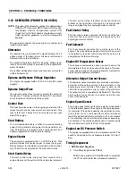
System Settings
CALL TO START SETTINGS
CURRENT AND VOLTAGE SETTINGS
TIME DELAY SETTINGS
CRANK SETTINGS
SPEED TIME AND GLOW PLUG SETTINGS
Normal output voltage level
58.0 VDC
Extend output voltage level
58.0 VDC
Current limit level
45 ADC
High voltage shutdown level
63 ADC
Finish charging current level
30 ADC
Low battery voltage call to start level
48.0 VDC
Low battery voltage remove call to start level
54.0 VDC
Low temperature call to start level
5°C
Low temperature remove call to start level
8°C
Low start battery voltage call to start level
12.2 V
Low start battery voltage remove call to start level
12.9 V
TD engine start
30s
TD purge
0s
TD bypass
10s
TD engine run
1800s
TD cool-down
30s
TD high volts
2s
Crank time
15s
Reset time
15s
Crank cycles
3
TD no speed signal
5s
TD DC sensing fault
10s
Starter disconnect
1000 Hz
Overspeed shutdown
3800 RPM
Underspeed shutdown
2000 RPM
Glow plug on temperature
5°C
Glow plug on time
15s
Содержание JLG E400AJP
Страница 2: ......
Страница 21: ...SECTION 1 SPECIFICATIONS 3121827 JLG Lift 1 7 Figure 1 2 Operator Maintenance Lubrication Diagram...
Страница 32: ...SECTION 1 SPECIFICATIONS 1 18 JLG Lift 3121827 NOTES...
Страница 42: ...SECTION 2 GENERAL 2 10 JLG Lift 3121827 NOTES...
Страница 54: ...SECTION 3 CHASSIS TURNTABLE 3 12 JLG Lift 3121827 Figure 3 3 Speed Sensor Orientation...
Страница 55: ...SECTION 3 CHASSIS TURNTABLE 3121827 JLG Lift 3 13 Figure 3 4 Frame Mounted Electrical Components Sheet 1 of 2...
Страница 56: ...SECTION 3 CHASSIS TURNTABLE 3 14 JLG Lift 3121827 Figure 3 5 Frame Mounted Electrical Components Sheet 2 of 2...
Страница 60: ...SECTION 3 CHASSIS TURNTABLE 3 18 JLG Lift 3121827 Figure 3 7 Steering Components and Spindles...
Страница 62: ...SECTION 3 CHASSIS TURNTABLE 3 20 JLG Lift 3121827 Figure 3 9 Tilt Sensor Location...
Страница 86: ...SECTION 3 CHASSIS TURNTABLE 3 44 JLG Lift 3121827 Figure 3 16 Swing Components...
Страница 88: ...SECTION 3 CHASSIS TURNTABLE 3 46 JLG Lift 3121827 Figure 3 18 Battery Cable Connections...
Страница 90: ...SECTION 3 CHASSIS TURNTABLE 3 48 JLG Lift 3121827 Figure 3 20 On Board Generator...
Страница 97: ...SECTION 3 CHASSIS TURNTABLE 3121827 JLG Lift 3 55 Figure 3 22 Generator Components...
Страница 100: ...SECTION 3 CHASSIS TURNTABLE 3 58 JLG Lift 3121827 Figure 3 23 Generator System Analyzer Flow Chart...
Страница 116: ...SECTION 3 CHASSIS TURNTABLE 3 74 JLG Lift 3121827 NOTES...
Страница 125: ...SECTION 4 BOOM PLATFORM 3121827 JLG Lift 4 9 Figure 4 8 Jib Platform Components and Attaching Hardware...
Страница 127: ...SECTION 4 BOOM PLATFORM 3121827 JLG Lift 4 11 Figure 4 10 Boom Limit Switches...
Страница 140: ...SECTION 4 BOOM PLATFORM 4 24 JLG Lift 3121827 Figure 4 13 Rotator Counterbalance Valve...
Страница 178: ...SECTION 5 HYDRAULICS 5 24 JLG Lift 3121827 Figure 5 26 HydraForce Cartridge Torque Value Chart...
Страница 179: ...SECTION 5 HYDRAULICS 3121827 JLG Lift 5 25 Figure 5 27 Main Valve Components Prior to S N 62642...
Страница 214: ...SECTION 6 JLG CONTROL SYSTEM 6 34 JLG Lift 3121827 NOTES...
Страница 257: ......


