background image

SECTION 7 - BASIC TROUBLESHOOTING, ELECTRICAL INFORMATION, & SCHEMATICS

7-42

– JLG Lift –

3121827

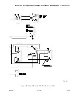
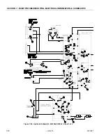
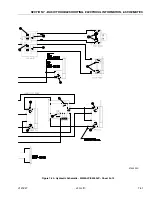
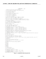
Figure 7-30.  Hydraulic Schematic Component List

Содержание JLG E400AJP

Страница 1: ...Service and Maintenance Manual Model E400A AJP E400A AJPnarrow M400A AJP M400A AJPnarrow P N 3121827 March 20 2014...

Страница 2: ......

Страница 3: ...OPER ATOR B HYDRAULIC SYSTEM SAFETY It should be noted that the machines hydraulic systems operate at extremely high potentially dangerous pres sures Every effort should be made to relieve any system...

Страница 4: ...st 15 2000 Revised October 1 2001 Revised December 18 2001 Revised April 11 2002 Revised May 24 2004 Revised September 17 2007 Revised January 21 2008 Revised January 27 2009 Revised January 7 2013 Re...

Страница 5: ...1 6 1 16 Lubrication 1 6 Lubrication Specifications 1 6 1 17 Operator Maintenance Lubrication 1 8 SECTION 2 GENERAL 2 1 Machine Preparation Inspection and Maintenance 2 1 General 2 1 Preparation Inspe...

Страница 6: ...isassembly 3 5 Disassembly of the first stage planetary assembly 7 3 5 Disassembly of second stage planet gears 1 3 5 Assembly of first stage planetary assembly 7 3 5 Assembly of end cover unit 8 3 5...

Страница 7: ...lgorithm 3 53 3 12 Generator Prior to S N 88539 3 54 Alternator 3 54 Dynamo and Dynamo Voltage Regulator 3 54 Dynamo Output Fuse 3 54 Control Fuse 3 54 Start Battery 3 54 Engine Starter 3 54 Start Con...

Страница 8: ...14 Supplementary fuse for apu 3 72 Tools And Material 3 72 Procedure 3 72 SECTION 4 BOOM PLATFORM 4 1 Boom Maintenance 4 1 Removal 4 1 Disassembly 4 1 Inspection 4 2 Assembly 4 2 Installation 4 3 4 2...

Страница 9: ...s in the Hydraulic System 5 1 Cup and Brush 5 1 Dip Method 5 2 Spray Method 5 2 Brush on Method 5 2 5 2 Cylinders Theory of Operation 5 3 Double Acting Cylinder 5 3 5 3 Cylinder Checking Procedures 5...

Страница 10: ...UBLESHOOTING ELECTRICAL INFORMATION SCHEMATICS 7 1 General 7 1 7 2 Troubleshooting 7 1 7 3 Multimeter Basics 7 19 Grounding 7 19 Backprobing 7 19 Min Max 7 19 Polarity 7 19 Scale 7 19 Voltage Measurem...

Страница 11: ...g Components and Spindles 3 18 3 8 Drive Components 3 19 3 9 Tilt Sensor Location 3 20 3 10 Swing Motor Cutaway 3 21 3 11 Swing Motor Exploded View 3 23 3 12 Swing Bearing Feeler Gauge Check 3 39 3 13...

Страница 12: ...on of Head Seal Kit 5 17 5 19 Piston Seal Kit Installation 5 17 5 20 Tapered Bushing Installation 5 18 5 21 Seating the Tapered Bearing 5 18 5 22 Poly Pak Piston Seal Installation 5 18 5 23 Rod Assemb...

Страница 13: ...Electrical Components Installation Sheet 2 7 31 7 20 Electrical Schematic Sheet 1 of 4 7 32 7 21 Electrical Schematic Sheet 2 of 4 7 33 7 22 Electrical Schematic Sheet 3 of 4 7 34 7 23 Electrical Sche...

Страница 14: ...rithms 3 53 3 5 RBS Prestart Sequence 3 56 3 6 RBS Startup Sequence 3 56 3 7 RBS Shutdown Sequence 3 56 3 8 Generator System Flash Codes 3 57 3 9 Controller Interface Pin Assignments 3 66 3 10 RBS Ala...

Страница 15: ...alffulloflubricant Table 1 3 Battery Charger Input 110VAC 60HZ Output 48VDC 25Amps Batteries 8 6Volt 370AmpHour 20hourrate Table 1 4 Drive System DriveMotor 48VDC 12 5 H P 3200rpm continuous rotation...

Страница 16: ...0in 0 61m 2ft 10in 0 86m 2ft 0in 0 61m 2ft 10in 0 86m TurningRadius outside 10ft 4in 3 15m Table 1 9 Function Speeds Function Seconds MainLiftUp 30 24 MainLiftDown 29 23 TurntableSwingRight Left360 81...

Страница 17: ...RM ROTATE Platform level and completely rotated one direction Rotate the opposite direction record time Rotate the other direction record time 7 JIB Platform level and centered with the boom Start wit...

Страница 18: ...1 1 00 25 4 MasterCylinder E M400AJP 3 00 75 11 5 292 1 25 32 SlaveCylinder E M400A 2 00 50 8 9 375 238 1 1 00 25 4 SlaveCylinder E M400AJP 3 00 75 11 6 295 5 1 25 32 RotatorCylinder 1 875 47 6 15 250...

Страница 19: ...Main Relief E400AJ M400AJ 3400 234 Jib Valve Jib Relief Up andDown 1500 103 Jib Swing Relief 3000 207 Releveling Valve Releveling Relief 1200 83 Table 1 15 Pressure Settings S N 0300062642 to Present...

Страница 20: ...same required additives or be of comparable viscosities If use of hydraulic oil other than Mobil DTE 11M is desired contact JLG Indus tries for proper recommendations Lubrication Specifications NOTE R...

Страница 21: ...SECTION 1 SPECIFICATIONS 3121827 JLG Lift 1 7 Figure 1 2 Operator Maintenance Lubrication Diagram...

Страница 22: ...raulic Tank Lube Point s Fill Cap Capacity 4 Gal 15 1 L Lube HO Interval Check Level daily Change every 2 years or 1200 hours of operation Comments On new machines those recently over hauled or after...

Страница 23: ...Interval Check level every 3 months or 150 hrs of operation change every 2 years or 1200 hours of operation 6 Wheel Bearings Lube Point s Repack Capacity A R Lube MPG Interval Every 2 years or 1200 h...

Страница 24: ...FICATIONS 1 10 JLG Lift 3121827 9 Engine Lube Point s Fill Cap Capacity Refer to Engine Manual Lube EO Interval 3 Months or 150 hours of operation Comments Check level daily Change in accor dance with...

Страница 25: ...2 0 5625 0 1820 11600 110 149 80 108 120 163 98 133 18 0 5625 0 2030 12950 120 163 90 122 135 184 109 148 5 8 11 0 6250 0 2260 14400 150 203 110 149 165 224 135 183 18 0 6250 0 2560 16300 170 230 130...

Страница 26: ...VALUES ARE STATIC TORQUE MEASURED PER STANDARD AUDIT METHODS TOLERANCE 10 LB IN LB N m IN LB N m IN LB N m 1320 43 5 1580 60 7 1800 68 8 2860 143 16 129 15 3280 164 19 148 17 LB FT LB N m FT LB N m F...

Страница 27: ...485 335 455 315 430 7 8 9 0 8750 0 4620 41600 515 700 485 660 455 620 14 0 8750 0 5090 45800 570 775 535 730 500 680 1 8 1 0000 0 6060 51500 730 995 685 930 645 875 12 1 0000 0 6630 59700 845 1150 795...

Страница 28: ...515 315 430 7 8 9 0 8750 0 4620 41600 605 825 545 740 455 620 14 0 8750 0 5090 45800 670 910 600 815 500 680 1 8 1 0000 0 6060 51500 860 1170 775 1055 645 875 12 1 0000 0 6630 59700 995 1355 895 1215...

Страница 29: ...157 68 3 219 164 197 241 18 2 5 192 83 5 301 226 271 331 20 2 5 245 106 5 426 320 383 469 22 2 5 303 132 0 581 436 523 639 24 3 353 153 5 737 553 663 811 27 3 459 199 5 1080 810 970 1130 30 3 5 561 2...

Страница 30: ...19 5 430 385 325 20 2 5 245 152 5 610 550 460 22 2 5 303 189 0 830 750 625 24 3 353 222 0 1065 960 800 27 3 459 286 0 1545 1390 1160 30 3 5 561 349 5 2095 1885 1575 33 3 5 694 432 5 2855 2570 2140 36...

Страница 31: ...5 365 345 325 20 2 5 245 152 5 520 490 460 22 2 5 303 189 0 705 665 625 24 3 353 220 0 900 845 790 27 3 459 286 0 1315 1235 1160 30 3 5 561 349 5 1780 1680 1575 33 3 5 694 432 5 2425 2285 2140 36 4 81...

Страница 32: ...SECTION 1 SPECIFICATIONS 1 18 JLG Lift 3121827 NOTES...

Страница 33: ...h machine in ser vice for 3 months or 150 hours whichever comes first out of service for a period of more than 3 months or when purchased used The frequency of this inspection must be increased as env...

Страница 34: ...r contain ers until they are ready to be used Components Removal and Installation 1 Use adjustable lifting devices whenever possible if mechanical assistance is required All slings chains cables etc s...

Страница 35: ...alues should be used on heat treated bolts studs and steel nuts in accor dance with recommended shop practices See Torque Chart Section 1 Hydraulic Lines and Electrical Wiring Clearly mark or tag hydr...

Страница 36: ...from the original container into another be sure to clean all possible contami nants from the service container Always clean the mesh element of the filter and replace the cartridge any time the syste...

Страница 37: ...e all grease and oil filament wound bearing are a dry joint and should not be lubri cated unless otherwise instructed i e sheave pins c Pins should be inspected to ensure it is free of burrs nicks and...

Страница 38: ...Bearings 1 2 1 2 WearPads 1 2 1 2 CoversorShields 1 2 1 2 Extend RetractChainorCableSystems 1 2 3 1 2 3 PlatformAssembly 9 Platform 1 2 1 2 Railing 1 2 1 1 2 Gate 5 1 1 5 Floor 1 2 1 1 2 Rotator 9 5...

Страница 39: ...harger 5 5 FuelReservoir Cap andBreather N A Hydraulic ElectricSystem 9 HydraulicPumps 1 9 1 2 9 HydraulicCylinders 1 9 7 2 1 2 9 1 2 9 CylinderAttachmentPinsandPinRetainers 1 9 1 2 1 2 HydraulicHoses...

Страница 40: ...nspection PerformanceCodes 1 Checkforproperandsecureinstallation 2 Visualinspectionfordamage cracks distortionorexcessivewear 3 Checkforproperadjustment 4 Checkforcrackedorbrokenwelds 5 OperatesProper...

Страница 41: ...PERATURES OF 100 F 38 C OR ABOVE EXTENDED DRIVING WITH HYDRAULIC OIL TANK TEMPERATURES OF 180 F 82 C OR ABOVE NO OPERATION BELOW THIS AMBIENT TEMPERATURE MOBIL 424 10W 30 HYDRAULIC SPECIFICATIONS NO O...

Страница 42: ...SECTION 2 GENERAL 2 10 JLG Lift 3121827 NOTES...

Страница 43: ...tics Equal or greater ply load rating and size of original Tire tread contact width equal or greater than original Wheel diameter width and offset dimensions equal to the original Approved for the app...

Страница 44: ...ch may have to be used to set the end play 6 The units should be checked visually to make sure the cotter pins are installed and that the correct components have been used Each unit must also be check...

Страница 45: ...SECTION 3 CHASSIS TURNTABLE 3121827 JLG Lift 3 3 1 DustCap 2 CotterPin 3 SpindleNut 4 Spindle Washer 5 Stud Nut 6 Bearing Cone 7 Hub 8 Bearing Cone 9 Seal 10 Spindle Figure 3 3 Spindle Assembly...

Страница 46: ...and remove the cover unit 8 from drive 9 Remove o ring 33 10 Remove the first stage planetary assembly 7 11 Remove hex bolts 23 12 Remove ring gear 30 and o ring 19 13 Remove snap rings 15 14 Pull of...

Страница 47: ...al roller bearings out of planet gears 1 Assembly of first stage planetary assembly 7 1 Pre freeze planet pins 5 and install into planet car rier 7 2 Install planet carrier 7 together with planet pins...

Страница 48: ...the oil level plug which should be removed before oil fill With the gear case filled to their proper levels start the machine and allow sufficient time for run in at moderate pressure and speed befor...

Страница 49: ...RingSeal 21 ScrewPlug 22 Seal Ring 23 Bolt 24 Ball 25 Expander 26 thru28 NotUsed 29 Washer 30 RingGear 31 thru32 NotUsed 33 ORing 34 Spring 35 thru42 NotUsed 43 SunGearShaft 44 InputShaft 45 thru48 No...

Страница 50: ...nstall shaft assembly and retaining ring 17 in cover 21 NOTE Be sure to use the same number of springs and spring pattern as recorded during disassembly This should be five red springs evenly spaced 5...

Страница 51: ...ring 6 BackupRing 7 Piston 8 O ring 9 BackupRing 10 Shaft 11 StatorDisc 12 SensorRing 13 RotorDisc 14 Plate 15 Spring 16 Spring Retainer 17 Retaining Ring 18 Bearing 19 RetainingRing 20 DowelPin 21 C...

Страница 52: ...urrence Seespringreplacement Brakedragsorruns hot Lowactuationpressure Thebrakeshouldbepressurizedtominimumof 1 38bar 20psi overthefullreleasepressureunder normaloperatingconditions Lowerpressureswill...

Страница 53: ...IS SELECTED THE MACHINE WILL NOT STOP UNLESS THE FOOT SWITCH IS RELEASED OR THE EMS IS PUSHED IN IF ONLY ONE SENSOR IS INSTALLED WRONG THE CONTROL LER SENSES A PROBLEM AND THE MACHINE WILL ONLY DRIVE...

Страница 54: ...SECTION 3 CHASSIS TURNTABLE 3 12 JLG Lift 3121827 Figure 3 3 Speed Sensor Orientation...

Страница 55: ...SECTION 3 CHASSIS TURNTABLE 3121827 JLG Lift 3 13 Figure 3 4 Frame Mounted Electrical Components Sheet 1 of 2...

Страница 56: ...SECTION 3 CHASSIS TURNTABLE 3 14 JLG Lift 3121827 Figure 3 5 Frame Mounted Electrical Components Sheet 2 of 2...

Страница 57: ...m p C ircuit If the voltage is high check for corrosion a dirty pum p m otor or bad brushes T he drive system should show 48 volts w ith the m ain contactor closed and 35 volts w ith the m ain contact...

Страница 58: ...RSTAND THIS ENTIRE PROCEDURE PRIOR TO BEGINNING 1 Before beginning this procedure insure that there is at least 10 ft 3m in front and back of machine Be sure that all other personnel stand clear of th...

Страница 59: ...ustment Procedure until the analyzer displays SPEED 20 FWD when forward is selected in the platform The percentage displayed is not critical just the direction 22 After obtaining the display in step 1...

Страница 60: ...SECTION 3 CHASSIS TURNTABLE 3 18 JLG Lift 3121827 Figure 3 7 Steering Components and Spindles...

Страница 61: ...a flat level surface Check for level by placing a bubble level on the frame in both directions 2 Plug in the analyzer Analyzer p n 1600244 Cable p n 1600633 into port J9 on the power module or port J1...

Страница 62: ...SECTION 3 CHASSIS TURNTABLE 3 20 JLG Lift 3121827 Figure 3 9 Tilt Sensor Location...

Страница 63: ...Lift 3 21 3 7 SWING MOTOR S N 0300135649 TO PRESENT IF THE HYDRAULIC SYSTEM FLUID BECOMES OVERHEATED IN EXCESS OF 200 F 93 3 C SEALS IN THE SYSTEM CAN SHRINK HARDEN OR CRACK THUS LOSING THEIR SEALING...

Страница 64: ...t Significantlossofspeedunderload 1 Lackofsufficientoil supply 2 High internal motorleakage 3 Severelywornordamagedinternalsplines 4 Excessiveheat a Checkforfaultyreliefvalveandadjustorreplaceas requi...

Страница 65: ...ommutator 6 CommutatorRing 7 Manifold 8 RotorSet 8A Rotor 8B StatorHalf 8C StatorVane 8D StatorHalf 9 WearPlate 10 DriveLink 11 ThrustBearing 12 CouplingShaft 13 InnerBushing 14 ThrustWasher 15 Thrust...

Страница 66: ...SOLVENTS ARE FLAMMABLE BE EXTREMELY CAREFUL WHEN USING ANY SOLVENT EVEN A SMALL EXPLO SION OR FIRE COULD CAUSE INJURY OR DEATH WEAR EYE PROTECTION AND BE SURE TO COMPLY WITH OSHA OR OTHER MAXIMUM AIR...

Страница 67: ...ry Be sure the end cover valve apertures are free of contamination Inspect end cover for cracks and the bolt head recesses for good bolt head sealing surfaces Replace end cover as neces sary NOTE A po...

Страница 68: ...g as a matched set 8 Remove manifold 7 and inspect for cracks surface scoring brinelling or spalling Replace manifold if any of these conditions exist A polished pattern on the ground surface from com...

Страница 69: ...grease pencil before removal will ensure correct reassembly of rotor into stator and rotor set into motor Marking all rotor components and mating spline components for exact reposition ing at assembly...

Страница 70: ...nspect coupling shaft bearing and seal surfaces for spalling nicks grooves severe wear or corrosion and discoloration Inspect for damaged or worn internal and external splines or keyway Replace coupli...

Страница 71: ...be removed without changing dimensional characteristics Inspect tapped holes for thread damage If the housing is defective in these areas discard the housing assem bly 19 If the housing 18 assembly ha...

Страница 72: ...laced use a suitable size bearing puller to remove bearing bushings 19 and 13 from hous ing 18 without damaging the housing Remove thrust washers 14 and thrust bearing 15 if they were previously retai...

Страница 73: ...ired depth of 0 151 0 161 inches 3 84 4 09 mm from the end of the bearing counterbore NOTE Bearing mandrel must be pressed against the let tered end of bearing shell Take care that the hous ing bore i...

Страница 74: ...ping against the mounting flange 5 Assemble a new backup ring 17 new backup washer 25 and new seal 16 with the seal lip fac ing toward the inside of the motor into their respec tive counterbores in ho...

Страница 75: ...t of clean grease to a new seal ring 4 and insert it into the housing 18 seal ring groove NOTE One or two alignment studs screwed finger tight into housing 18 bolt holes approximately 180 degrees apar...

Страница 76: ...de must be down against wear plate for drive link clearance and to maintain the original rotor drive link spline contact A rotor set without a counterbore and that was not etched before disassembly ca...

Страница 77: ...ring 6 over alignment studs onto the manifold 18 Assemble a new seal ring 3 flat side up into com mutator 5 and assemble commutator over the end of drive link 10 onto manifold 7 with seal ring side u...

Страница 78: ...cover to radially align the end cover into its original position 20 Assemble the bolts 1 and screw in finger tight Remove and replace the two alignment studs with bolts after the other bolts are in p...

Страница 79: ...rotor counterbore down if applicable into stator and onto wear plate 9 with rotor splines into mesh with drive link 10 splines 4 Assemble six vanes or as many vanes that will read ily assemble into th...

Страница 80: ...en vanes using minimum force 6 Place second stator half on a fl at surface with seal ring groove up Apply a small amount of grease to a new seal ring 4 and assemble it into stator half ring groove 7 A...

Страница 81: ...ions indicated on Figure 3 12 try and insert the 0 0015 feeler gauge between the bolt head and hardened washer at the arrow indi cated position c Assure that the 0 0015 feeler gauge will not penetrate...

Страница 82: ...e dial indicator measure and record the distance between the swing bearing and turntable See Figure 3 14 2 At the same point with the boom positioned over the side of the machine the Upper Boom fully...

Страница 83: ...the frame Discard the bolts Use suitable lifting equipment to remove the bearing and rotation box assem bly from the frame move to a clean suitably supported work area h Remove the two capscrews secur...

Страница 84: ...ribed line of the inner race of the bearing aligns with the scribed mark on the turntable If a new swing bearing is used ensure that the filler plug fitting is at 90 degrees from the fore and aft cent...

Страница 85: ...rance exceeds 0 010 reduce end play to less than 0 005 Refer to Adjusting End Play Adjusting End Play 1 Remove end plate 2 Measure and record total thickness of existing shim pack 3 Determine thicknes...

Страница 86: ...SECTION 3 CHASSIS TURNTABLE 3 44 JLG Lift 3121827 Figure 3 16 Swing Components...

Страница 87: ...nt caps 3 Remove battery cables from each battery post one at a time negative first Clean cables with acid neu tralizing solution e g baking soda and water or ammonia and wire brush Replace cables and...

Страница 88: ...SECTION 3 CHASSIS TURNTABLE 3 46 JLG Lift 3121827 Figure 3 18 Battery Cable Connections...

Страница 89: ...l take approximately 17 hours to charge Optional On Board Generator EXHAUST GAS HAZARD RUN THE GENERATOR IN A WELL VENTI LATED AREA ONLY WHEN THE GENERATOR ENABLE CONTROL LOCATED IN THE PLATFORM CONTR...

Страница 90: ...SECTION 3 CHASSIS TURNTABLE 3 48 JLG Lift 3121827 Figure 3 20 On Board Generator...

Страница 91: ...he charger may now be unplugged from AC power If left plugged in the charger will automatically restart a complete charge cycle if battery voltage drops below a minimum volt age or 30 days have elapse...

Страница 92: ...TION 3 CHASSIS TURNTABLE 3 50 JLG Lift 3121827 1 2 3 4 1 ACVoltage InputCable 2 ChargerInterlockCable 3 DCPowerCableto Batteries 4 LED IndicatorCable Figure 3 21 Battery Charger S N 0300059350 to Pres...

Страница 93: ...s Confirm that a nomi nal battery voltage is the same as the charger volt age 3 This fault will clear automatically when the low bat tery voltage problem is rectified 4 If this problem does not clear...

Страница 94: ...blows If the green wire is shorted to ground even momentarily this fuse will blow To check the fuse measure with an ohmmeter between the green and red wires with the AC disconnected If a short circuit...

Страница 95: ...nector from the battery pack Apply AC power and after the LED test the Algorithm will display for 11 seconds 2 To change the algorithm touch the connector to the battery s positive terminal for 3 seco...

Страница 96: ...the pull coil of the engine fuel solenoid The start control relay is located on the fuel solenoid bracket on the right side of the engine The start control relay is energized by the engine generator c...

Страница 97: ...SECTION 3 CHASSIS TURNTABLE 3121827 JLG Lift 3 55 Figure 3 22 Generator Components...

Страница 98: ...perating conditions before enabling these shutdowns are monitored RBS Shutdown Sequence Once all CTS conditions have been removed the RBS will begin the shutdown sequence If a CTS condition is initi a...

Страница 99: ...reset once the fault has been cor rected Low Oil Pressure Enabled once TDBP time delay bypass period has elapsed after engine startup If the low engine oil pressure switch closes the engine will stop...

Страница 100: ...SECTION 3 CHASSIS TURNTABLE 3 58 JLG Lift 3121827 Figure 3 23 Generator System Analyzer Flow Chart...

Страница 101: ...to voltage regulator Loss Of Voltage Sense If the voltage measured at the alternator output is less than half of the system nominal voltage the RBS will stop immediately and an RBS loss of voltage sen...

Страница 102: ...n up any spilled fuel and try to start the genera tor engine 6 If the engine still doesn t start remove the steel line from the fuel injector pump 7 Once fuel starts to flow re connect the fuel line t...

Страница 103: ...3 phase AC output of the alternator is full wave recti fied and presented to the output terminals Output rating 58 0V at 45A Voltage regulation and current limiting is provided by the RBS Engine Gene...

Страница 104: ...10 5 4 1 2 6 3 13 14 Figure 3 24 Generator 8 TemperatureSensor 9 VoltageRegulator 10 Alternator 11 Starter 12 StarterSolenoid 13 Oil Filter 14 Fuel Filter 1 GlowPlug Relay 2 Fuel Control Relay 3 Start...

Страница 105: ...equipped with a 12VDC starter which pro vides the mechanical power to crank the engine Electrical power for the starter is provided by the start battery The starter is energized by the start control...

Страница 106: ...racket on the right side of the engine Glow Plug Control Relay The glow plug control relay energizes the glow plug It is energized by the engine generator controller pin J2 27 The glow plug control re...

Страница 107: ...d has a pull coil energized by the start control relay and a hold coil energized by the fuel control relay The fuel solenoid is located on the right side of the engine Engine Low Oil Pressure Switch T...

Страница 108: ...erspeed fault If the signal is not present at the engine generator controller the unit will fault with a loss of speed signal indication The engine speed sensor is connected to the engine gen erator c...

Страница 109: ...atus and performance can be monitored by the analyzer System Settings CALL TO START SETTINGS CURRENT AND VOLTAGE SETTINGS TIME DELAY SETTINGS CRANK SETTINGS SPEED TIME AND GLOW PLUG SETTINGS Normalout...

Страница 110: ...nestarts orOvercrankfault is indicatedafter3failed crank cycles Time delaybypass RBSwaitsuntilnormalengine operating conditions are reachedbeforeLowoilpressure andUnderspeedfaultsaremoni tored Call to...

Страница 111: ...wn 1 2 HighEngineTemp Over248 F 120 C Shutdown 1 3 Overspeed Over3800RPM Shutdown 1 4 Underspeed1 Below2000RPM Shutdown Overcrank 3failedcrankcyclesCall tostartremoved Call tostartremoved 1 5 No Speed...

Страница 112: ...thedesign limitsoftheengine Verifycorrectoperation ofenginetemperature sensor 1 3 Overspeed Verifysetting ofgovernorlever Readjust ifrequired Refer toKubotaWorkshopmanual WSMOC60 80 95 1 4 Underspeed...

Страница 113: ...ACID LEVEL IN THE BATTERY THE VOLTAGE OF THE BOOSTER BATTERY MUST BE RATED AT 12V THE AMP HOUR CAPACITY OF THE BOOSTER BATTERY MUST NOT BE LOWER OR SUBSTANTIALLY HIGHER THAN THAT OF THE DISCHARGED BAT...

Страница 114: ...rocedure BEFORE BEGINNING THIS PROCEDURE ENSURE THAT ALL SOURCES OF POWER ARE DISCONNECTED FROM THE APU This procedure is common for all applications of the APU The photos contained in this document i...

Страница 115: ...e Generator Control ler after the existing connection point and install the conductors that lead to the new inline fuse holder Use insulated butt splice connectors for these con ductors 6 Re install t...

Страница 116: ...SECTION 3 CHASSIS TURNTABLE 3 74 JLG Lift 3121827 NOTES...

Страница 117: ...INANTS INTO SYSTEM b Tag and disconnect hydraulic lines from boom to control valve Use a suitable container to retain any residual hydraulic fluid Cap hydraulic lines and ports c Using a suitable lift...

Страница 118: ...6 Remove hardware securing power track to the base boom section Remove power track Inspection 1 Inspect boom pivot pin for wear scoring or other damage and for tapering or ovality Replace pin as neces...

Страница 119: ...ernately side to side so that fly boom section is centered in base boom section 14 Retract boom section fully Adjust wear pads at aft end of boom section to zero clearance Adjust pads alternately side...

Страница 120: ...ware 3 Remove cylinder port plugs and hydraulic line caps and correctly attach lines to cylinder ports 4 With function speed switch at its slowest setting extend the cylinder rod until attach pin hol...

Страница 121: ...g slings restrain the lower lift cylinder 3 Remove the hardware securing the cylinder rod attach pin 5 to the boom Using an appropriate brass drift drive out the cylinder rod attach pin 5 4 Tag discon...

Страница 122: ...efully drive the tele scope cylinder pin from the base boom 8 Attach a suitable sling to the telescope cylinder Using a suitable lifting device attached to the sling carefully pull the telescope cylin...

Страница 123: ...ng in the port block 3 From the platform turn the speed control knob to the slow position 4 Lift up very slowly This will force any air out of the circuit If the lower boom is not extending turn the s...

Страница 124: ...boom pivot weldment 2 Remove mounting hardware from rotator support and jib lift cylinder pins 5 and 6 Using a suitable brass drift and hammer remove the pins from rotator support Inspection 1 Inspect...

Страница 125: ...SECTION 4 BOOM PLATFORM 3121827 JLG Lift 4 9 Figure 4 8 Jib Platform Components and Attaching Hardware...

Страница 126: ...ot weldment and secure with mounting hardware 5 Align articulating jib boom pivot weldment with attach holes in fly boom assembly Using a soft head mallet install pivot pin 2 into fly boom assembly an...

Страница 127: ...SECTION 4 BOOM PLATFORM 3121827 JLG Lift 4 11 Figure 4 10 Boom Limit Switches...

Страница 128: ...n is displaced axially within the housing similar to the operation of a hydraulic cylinder while the splines cause the shaft to rotate When the con trol valve is closed oil is trapped inside the actua...

Страница 129: ...ng 2 Shaft 3 PistonSleeve 4 EndCap 109 LockPin 113 CapScrew 200 T Seal 202 T Seal 204 O Ring 205 Cup Seal 207 Back Up 302 WearGuide 304 ThrustWasher 304 1 WiperSeal 400 StopTube Optional 401 Counterba...

Страница 130: ...ing 2 Shaft 3 PistonSleeve 4 EndCap 109 LockPin 113 CapScrew 200 T Seal 202 T Seal 204 O Ring 205 Cup Seal 207 Back Up 302 WearGuide 304 ThrustWasher 304 1 WiperSeal 400 StopTube Optional 401 Counterb...

Страница 131: ...tion of piston sleeve 9 End cap dowel pins removal and installation of end cap sold with Helac seal kit The seal tool is merely a customized standard flat head screwdriver To make this tool you will n...

Страница 132: ...sing a metal bar or something similar un screw the end cap 4 by turning it counter clock wise 6 Remove the end cap 4 and set aside for later inspection 7 Remove the stop tube if included The stop tube...

Страница 133: ...1 Before removing the piston 3 mark the housing 1 ring gear in relation to the piston O D gear There should now be timing marks on the housing 1 ring gear the piston 3 and the shaft 2 12 To remove the...

Страница 134: ...is easi est to cut them using a sharp razor blade being careful not to damage the seal groove 17 Remove the thrust washers 304 from the end cap 4 and shaft 2 18 Remove the wiper seal 304 1 from its g...

Страница 135: ...n edges and surfaces Measure it s thickness to make sure it is within specifications Not less than 0 092 or 2 34 mm 3 Inspect the wear guide condition and measure thick ness not less than 0 123 or 3 1...

Страница 136: ...p rings see drawing for ori entation 7 Beginning with the inner seal 200 insert one end of b u ring in the lower groove and feed the rest in using a circular motion Make sure the wedged ends overlap c...

Страница 137: ...Looking from the view shown use the existing tim ing marks to line up the gear teeth on the shaft 2 with the gear teeth on the inside of the piston 3 Now tap the flange end of the shaft with a rubber...

Страница 138: ...uide stays in place on the end cap as it is threaded into the housing 1 18 Tighten the end cap 4 In most cases the original holes for the lock pins will line up 19 Place the lock pins 109 provided in...

Страница 139: ...ydraulic test bench The breakaway pressure the pressure at which the shaft begins to rotate should be approximately 400 psi 28 bar Cycle the actuator at least 25 times at 3000 psi 210 bar pressure Aft...

Страница 140: ...SECTION 4 BOOM PLATFORM 4 24 JLG Lift 3121827 Figure 4 13 Rotator Counterbalance Valve...

Страница 141: ...liters is purged 1 Connect a 3 16 inside diameter x 5 16 outside diameter x 5 foot clear vinyl drain tube to each of the two bleed nipples Secure them with hose clamps Place the vinyl tubes in a clea...

Страница 142: ...nonpage24ofthismanual e Re buildtheactuator Removeallrustthenpol ish Replacementpartsmaybeneeded f Re buildtheactuator Usefluidthatiscompati blewithsealsandbearings 2 Operationis erraticornot responsi...

Страница 143: ...only Actual hose and cable arrangements will be differ ent 1 Clamp the bar and poly roller tightly so they do not spin when removing the screw With a small ratchet and a t 20 torx bit remove the 8 32...

Страница 144: ...t bur attachment MOVE THE CABLES HOSES OUT OF THE WAY DURING THE GRINDING PROCESS TO PROTECT THEM KEEP THE HOSES AND CABLES COVERED TO PREVENT ANY DEBRIS FROM GETTING ON THEM 4 insert the tool into th...

Страница 145: ...rivet out by using a center punch with a hammer NOTE It may be necessary to loosen the fixed end brackets from the machine in order to twist and pull the track section enough to disconnect the links 6...

Страница 146: ...4 30 JLG Lift 3121827 7 Remove the link from the other section of the pow ertrack using a screwdriver Installing a New Link 1 Squeeze the peanut cut out end of the new link into the half shear female...

Страница 147: ...the half shear female end of the new link and slide the peanut end of the track section into it a screwdriver may be necessary to do this 3 After the new link is installed in the powertrack the round...

Страница 148: ...ack so that the new connection is positioned in the curve of the powertrack In this position the round half shears will rotate into the peanut cut outs 5 The parts shown below will be used to connect...

Страница 149: ...stallation steps for all center holes that have the rivets removed NOTE When installing snap rings make sure they are seated in pin groove and closed properly 8 Hold new aluminum round bar tightly the...

Страница 150: ...SECTION 4 BOOM PLATFORM 4 34 JLG Lift 3121827 NOTE Maximum tightening torque is 18 20 in lbs 9 Pull up on the other end of the round bar and slide the new poly roller onto the bar...

Страница 151: ...nst link with no space in between the link and underside of screw head Maximum tightening torque is 18 20 in lbs Replacing Fixed End Brackets 1 Remove the rivets the same way as shown under the link r...

Страница 152: ...nd Center Pin Snap Ring 3 Take the new bracket and install bracket center pin and snap ring Repeat on the other bracket if replac ing it as well NOTE When installing snap rings make sure they are seat...

Страница 153: ...e rivet the same way as shown in the link removal instructions Repeat on other bracket if replacing it as well MOVE THE CABLES HOSES OUT OF THE WAY DURING THE GRINDING PROCESS TO PROTECT THEM KEEP THE...

Страница 154: ...inal locations and install snap rings Repeat with other moving end if replacing as well NOTE When installing snap rings make sure they are seated in pin groove and closed properly 4 When complete make...

Страница 155: ...he following is needed to correctly oil the o ring in this manner A small container for hydraulic oil Small paint brush 1 Hold the fitting in one hand while using the brush with the other hand to dip...

Страница 156: ...bottom of the fitting This should signify an even coating of oil on the fitting 3 O ring Boss type fittings will require more pressure in able to immerse more of the fitting into the satu rated sponge...

Страница 157: ...cylinder fully retracted shut down motor and carefully disconnect hydraulic hose from cylinder extend port 6 Activate hydraulic system and activate cylinder retract function Check extend port for leak...

Страница 158: ...1 Loctite 242 2 Loctite 222 3 Primer 7471 4 LoctiteRC609 5 Bolt 6 TaperedBushing 7 Bearing 8 Bushing 9 CylinderHead 10 Barrel 11 CylinderRod 12 WasherRing 13 O ring Plug 14 Piston 15 NotUsed 16 Backu...

Страница 159: ...ston 5 CylinderHead 6 Hex Nut 7 Tube Spacer 8 HoldingValve 9 Setscrew 10 Pipe Plug 11 T Seal 12 WearRing 13 O ring 14 O ring 15 WearRing 16 RodSeal 17 Wiper 18 Locking Primer 19 Loctite 242 20 Loctite...

Страница 160: ...lt 4 TaperedBushing 5 Bushing 6 CylinderHead 7 CylinderRod 8 Barrel 9 WasherRing 10 Piston 11 NotUsed 12 LockRing 13 WearRing 14 Backup Ring 15 O ring 16 O ring 17 Wiper 18 Seal 19 Backup Ring 20 Seal...

Страница 161: ...iston 5 CylinderHead 6 Hex Nut 7 TubeSpacer 8 HoldingValve 9 HoldingValve 10 Pipe Plug 11 Setscrew 12 PistonSeal 13 WearRing 14 O ring 15 WearRing 16 O ring 17 RodSeal 18 Wiper 19 Not Used 20 Loctite...

Страница 162: ...CylinderHead 6 Hex Nut 7 Washer 8 Spacer 9 Holding Valve 10 Holding Valve 11 Plug 12 Setscrew 13 LockRing 14 PistonSeal 15 NotUsed 16 NotUsed 17 O ring 18 Backup Ring 19 RodSeal 20 RodWiper 21 Loctite...

Страница 163: ...ap 4 Piston 5 CylinderHead 6 Hex Nut 7 TubeSpacer 8 NotUsed 9 HoldingValve 10 O ringPlug 11 Setscrew 12 Setscrew 13 WearRing 14 Seal 15 O ring 16 WearRing 17 O ring 18 Seal 19 Wiper 20 Loctite 242 21...

Страница 164: ...rrel 2 CylinderRod 3 Retainer 4 Piston 5 CylinderHead 6 Hex Nut 7 TubeSpacer 8 Setscrew 9 T Seal 10 WearRing 11 O ring 12 O ring 13 WearRing 14 RodSeal 15 RodWiper 16 Locking Primer 17 Loctite 242 18...

Страница 165: ...2 LockingPrimer 3 Bolt 4 Tapered Bushing 5 Bushing 6 Piston 7 Washer 8 Head 9 Barrel 10 CylinderRod 11 Not Used 12 LockRing 13 WearRing 14 Backup Ring 15 O ring 16 O ring 17 Wiper 18 Seal 19 Backup R...

Страница 166: ...5 12 JLG Lift 3121827 1 Wiper 2 SpannerNut 3 RetainingRing 4 Lip Seal 5 WearRing 6 Backup Ring 7 O ring 8 Guide 9 Barrel 10 Tube 11 Piston 12 WearRing 13 Seal 14 O ring 15 O ring 16 Rod 17 Rod Figure...

Страница 167: ...eValve 7 Bolt 8 Plug 9 Setscrew 10 Locknut 11 RetainingRing 12 WearRing 13 CapSeal 14 O Ring 15 WearRing 16 O ring 17 Rod Seal 18 Wiper 19 Loctite 242 20 NotUsed 21 Fitting 22 Cap 23 O Ring Plug 24 Bo...

Страница 168: ...leaking the piston seals are defective and must be replaced If the extend port is leaking the counterbalance is defective and must be replaced 5 To check piston seals carefully remove the counter bala...

Страница 169: ...bushing to the piston 11 Insert the cap screw s in the threaded holes in the outer piece of the tapered bushing Progressively tighten the cap screw s until the bushing is loose on the piston 12 Remove...

Страница 170: ...aced c Lubricate inside of the steel bushing with WD40 prior to bearing installation d Using an arbor of the correct size carefully press the bearing into steel bushing NOTE Install pin into the Gar M...

Страница 171: ...pplicable correctly place new seals and guide lock rings in the outer piston diameter groove A tube with I D slightly larger than the O D of the pis ton is recommended to install the solid seal NOTE T...

Страница 172: ...n the cap screws b Tap each space once this means the tapered bushing is tapped 3 times as there are 3 spaces between the cap screws 14 Retorque the cap screws evenly and progressively in rotation to...

Страница 173: ...r Head and Tapered Bushing Torque Specifications Description Head Torque Value Wet Tapered Bushing Torque Value Wet Jib Cylinder 41 Nm 30 ft lbs 7 Nm 5 ft lbs Level Cylinder 41 Nm 30 ft lbs 7 Nm 5 ft...

Страница 174: ...ettings S N 0300062642 to Present Lower Lift Down Relief 1 With pressure gauge at G port on main valve acti vate and bottom out Mid Lower Lift Down 2 Adjust Mid Lower Lift Relief to value given in Tab...

Страница 175: ...2 Adjust the Jib LIft pressure to the value given in Table 5 4 Pressure Settings Prior to S N 0300062642 or Table 5 5 Pressure Settings S N 0300062642 to Present Jib Swing Relief 1 Install the pressur...

Страница 176: ...sent Circuit PSI Bar MainControlValve LiftDownRelief 800 55 TowerLift Down Relief E M400A Priorto S N 86022 1700 117 TowerLift Down Relief E M400A S N 86022 to Present 2600 179 TowerLift Down Relief E...

Страница 177: ...G Lift 5 23 GAUGE PORT STEER RELIEF MAIN RELIEF SHUTTLE CARTRIDGE HYDRAULIC FILTER CHECK CARTRIDGE BRAKE RELEASE CARTRIDGE STEER CARTRIDGE PROPORTIONAL FLOW CONTROL CARTRIDGE PRESSURE SWITCH Figure 5...

Страница 178: ...SECTION 5 HYDRAULICS 5 24 JLG Lift 3121827 Figure 5 26 HydraForce Cartridge Torque Value Chart...

Страница 179: ...SECTION 5 HYDRAULICS 3121827 JLG Lift 5 25 Figure 5 27 Main Valve Components Prior to S N 62642...

Страница 180: ...HAND PUMP EMERGENCY DESCENT VALVE LOWER LIFT DOWN RELIEF RELEVELING RELIEF RELEVELING VALVE UPPER LIFT DOWN RELIEF TELESCOPE RELIEF GAUGE PORT PLATFORM LEVEL RELIEF BACKWARD PLATFORM LEVEL RELIEF FOR...

Страница 181: ...uced the need for exposed terminal strips diodes and trimpots and provides simplicity in viewing and adjusting the various personality settings for smooth control of acceleration deceleration creep an...

Страница 182: ...y two lines of information at a time by scrolling through the program NOTE Each module has a label with the JLG part number and a serial number which contains a date code The following instructions ar...

Страница 183: ...station the display will read GROUND OK If ENTER is pressed again the display moves to the fol lowing display LOGGED HELP 1 STARTUP 2 1 At this point the analyzer will display the last fault the sys t...

Страница 184: ...u For example MENU ACCESS LEVEL 2 Press ENTER to select the ACCESS LEVEL menu Using the UP or DOWN arrow keys enter the first digit of the password 3 Then using the RIGHT arrow key position the cursor...

Страница 185: ...t operation The Value will not increase if the UP arrow is pressed when at the maximum value nor will the value decrease if the DOWN arrow is pressed and the value is at the minimum value for any part...

Страница 186: ...cess to level 1 which will permit you to change all machine person ality settings There is a setting that JLG strongly recommends that you do not change This setting is so noted below ELEVATION CUTBAC...

Страница 187: ...5 MINimum UP speed 0 to 30 19 MAXimum UP speed 0 to 100 95 MINimum DOWN speed 0 to 20 7 MAXimum DOWN speed 0 to 100 47 UPPER LIFT ACCELeration 0 5 to 5 0 2 0 DECELeration 0 1 to 3 0 1 0 MlNimum UP sp...

Страница 188: ...T ROTATE ACCELeration 0 5 to 5 0 1 5 DECELeration 0 1 to 3 0 1 0 MlNimum LEFT speed 0 to 15 2 MAXimum LEFT speed 0 to 100 23 MINimum RIGHT speed 0 to 15 2 MAXimum RIGHT speed 0 to 100 27 JIB ACCELerat...

Страница 189: ...DOWN speed 0 to 100 36 UPPER LIFT speed 0 to 100 51 SWING speed 0 to 100 19 TELEscope speed 0 to 100 53 BASKET ROTATE speed 0 to 100 21 BASKET LEVEL speed 0 to 100 30 JIB SWING speed 0 to 100 42 JIB L...

Страница 190: ...and above elevation Reduces drive speed to creep when tilted only Option NOTE Any of the selections above will light the tilt lamp when a tilted condition occurs and will sound the platform alarm when...

Страница 191: ...VEHICLE EXCEPT ON A LEVEL SURFACE LEVEL VEHICLE YES ENTER NO ESC Not available at password level 2 ENTER confirms that vehicle is currently level and zeroes the tilt sensor mea surements Help Descrip...

Страница 192: ...ds are limited to cutback speed because the vehicle is above elevation RUNNING AT CREEP TILTED AND ABOVE ELEVATION All function speeds are limited to creep because the vehicle it tilted and above elev...

Страница 193: ...port 2 3 Flash code 2 3 indicates problems with boom function selection LIFT SWING JOYSTICK FAULTY The lift or swing Joystick center tap is out of valid range or the wiper is wire off LIFT SWING LOCK...

Страница 194: ...with the positrac tilt module the controller defaults to massively tilted and does not try to prevent vehicle roll on the grade 3 1 Flash code 3 1 indicates that a contactor did not close when energiz...

Страница 195: ...oller does not shut down BATTERY TOO HIGH SYSTEM SHUT DOWN Battery voltage is above 62V EMS recycle required BATTERY TOO LOW SYSTEM SHUT DOWN Battery voltage is below 33V EMS recycle required 5 5 Flas...

Страница 196: ...A is collapsing when the traction MOSFETs are pulsed This is probably due to an open cir cuit traction motor or a power wiring error NOTE This fault is unlikely to be seen due to interaction with spee...

Страница 197: ...ardware fail safe remained tripped when the traction MOS FETs were turned off POWER MODULE FAILURE HWFS CODE 14 The hardware fail safe tests failed because the line contactor could still be energized...

Страница 198: ...YSTEM FSW2 OPEN SYSTEM DRIVE CUTOUT OP SYSTEM ELEV CUTOUT OP SYSTEM DOS OFF SYSTEM BRAKES LOW PRES SYSTEM MAN RELEASE OP SYSTEM TILT 99 9 99 9 DIAGNOSTICS DATALOG DATALOG MAX TEMP 53c DATALOG MIN TEMP...

Страница 199: ...TELE MAX OUT 40 2 PLATFORM LEVEL ACCEL 1 0s 2 PLATFORM LEVEL DECEL 1 0s 2 PLATFORM LEVEL MIN UP 15 2 PLATFORM LEVEL MAX UP 30 2 PLATFORM LEVEL MIN DOWN 10 2 PLATFORM LEVEL MAX DOWN 22 2 PERSONALITIES...

Страница 200: ...MACHINE CALS 1 MACHINE CALS BRAKE 60 1 MACHINE CALS FLOW 0 30 1 MACHINE CALS FLOW 100 50 1 MACHINE CALS TLIFT 0 30 1 MACHINE CALS TLIFT 100 50 1 MACHINE CALS MLIFT 0 30 1 MACHINE CALS MLIFT 100 50 1...

Страница 201: ...ELE Displays telescope switch direction demand NOTE demand is controlled by the pump pot ROTATE Displaysbasketrotateswitchdirection demand NOTE demand is controlled by the pump pot JIB U D Displays ji...

Страница 202: ...ests he must simply press the enter key on the analyzer to con tinue 3 After the controller has conducted the tests from the chosen operator station it will display TESTS COM PLETE This indicates that...

Страница 203: ...is in use footswitch closed and for a short time afterwards RUN SYSTEM TEST ENTER starts system test Not available until tests are activated Displays messages while system test runs Some messages are...

Страница 204: ...uleandcontactorpanel BADPUMPWIRING PumppointAisnothigh probablycausedbyanopen circuitpumpmotororwiring Checkallpowerwiring Checkpumpmotor BADPOWERMODULE Aninternalproblemwasdetectedinthepowermodule BA...

Страница 205: ...mode theforward reversedirectioncontactorsareenergizedandde energized checksaremadethatthey close opencorrectlyandforshort circuitcoils Inplatformandgroundmode thelinecontactorisenergizedandde energiz...

Страница 206: ...efaulty Checkjoystick INPUTS DONE Indicatesthattheinputstestiscomplete withorwithoutfaults TESTING LAMPS Indicatesthatthelampstestisbeginning Eachlampisenergizedinturn apromptasksforconfirmationthatth...

Страница 207: ...ottestedifJIB NO Promptsdisplayedduringtheoperatorinputtestinclude CLOSEswitchname Thenamedswitchshouldbeclosed OPENswitchname Thenamedswitchshouldbeopened joysticknamedirectionTOMAX Thenamedjoysticks...

Страница 208: ...OBLEM HORN PERMANENTLYSELECTED Inputwas CLOSEDduringstartup 224 22 FUNCTIONPROBLEM STEERLEFT PERMANENTLY SELECTED TheSteerLeftSwitch wasclosed during power up 225 22 FUNCTIONPROBLEM STEERRIGHTPERMANEN...

Страница 209: ...startup 2265 22 FUNCTIONPROBLEM POSIDOWNPERMANENTLYSELECTED InputwasCLOSEDduringstartup 2266 22 LIFT SWINGJOYSTICK FAULTY Joystick wasoutoftheNeutral positionduringstartup 2267 22 DRIVE STEERJOYSTICK...

Страница 210: ...vationANDisconfiguredto preventdrive while tilted and aboveelevation 2552 25 LIFT UP PREVENTED TILTED ABOVEELEVATION Lift UP is notpossiblewhilethevehicleis tiltedandaboveeleva tion ANDisconfiguredto...

Страница 211: ...peedsensorfaultor faultsforNOVEHICLEMOVEMENTDETECTEDwith thevehicle onagrade 4610 46 RIGHTSPEEDSENSOR NOTRESPONDING PROPERLY Theright speed sensorisindicating animpossiblenumberof pulses this maybe du...

Страница 212: ...powermodule 826 82 RUNNINGATCREEP PLATFORMOVERLOADED Allfunctionsatcreep theLoadSensingSystemindicatesthe Platformis overloaded AND isconfigured to warnonlywhile the Platformis overloaded 827 82 DRIVE...

Страница 213: ...afaileddriverwithin the powermodule ora powerwiring error 99138 99 POWER MODULE FAILURE TEMPERATURE SENSOR Thetemperature sensormeasurementisinvalid thismaybedue toa disconnected wirewithinthepowermod...

Страница 214: ...SECTION 6 JLG CONTROL SYSTEM 6 34 JLG Lift 3121827 NOTES...

Страница 215: ...equipment and related systems It should be recognized that the majority of the problems arising in the machine will be centered in the hydraulic and electrical systems For this reason every effort has...

Страница 216: ...l s inslavelevelormainliftcylinder Replaceseal s Damagedslavelevelormainliftcylinder Repairorreplacecylinder Noresponsetoplatformlevelingcontrols Levelfunctionnotactivatedwithin7seconds afterfootswitc...

Страница 217: ...LECTRICAL INFORMATION SCHEMATICS 3121827 JLG Lift 7 3 ProportionalFlowRegulatornotpowered Checkwiring RunSystemTest Personalitiesnotsetcorrectly Checksettings Table 7 1 Platform Assembly Troubleshooti...

Страница 218: ...cessive pressurewithinvalve Checkpressuredeliverytoandfromvalveand repairorreplaceasnecessary Valveleaking Dirtorotherforeignmaterialunderseal Removeandrepairvalveasnecessary Valvespoolscored Removeva...

Страница 219: ...tionalvalvenotfunctioningproperly Repairorreplacevalve Pressurereliefvalvenotfunctioningproperly Re adjustorreplacevalve Liftcylindernotfunctioningproperly Repairorreplacecylinder Bindingliftcylindero...

Страница 220: ...amagedwiringoncontrolswitchorsolenoid valve Repairorreplacewiring RunSystemTest Directionalvalvenotfunctioningproperly Repairorreplacevalve Restrictedorbrokensupplylineonvalvebankor hydraulicpump Clea...

Страница 221: ...cknotfunctioning Repairorreplaceswingjoystick RunSystem Test Restrictedorbrokensupplylineonvalvebankor hydraulicpump Cleanorreplaceline Directionalvalvenotfunctioningproperly Repairorreplacevalve Swin...

Страница 222: ...ecessary Lackoflubricantonswinggearorspeedreducer pinion Lubricateasrequired SeeLubricationChart Swingmotornotfunctioningproperly Repairorreplaceswingcontrolswitch Wornorbrokenteethonswinggearorswing...

Страница 223: ...g Repairas necessary Valvespoolscored Removevalveandrepairorreplaceasneces sary Returnspringweakorbroken Removevalveandrepairorreplaceasneces sary Reliefvalvemalfunctioningcausingexcessive pressurewit...

Страница 224: ...erycable s notmakingcontact Cleanandtightencable s Enginewillnotstart ignitionOK Nofuel Replenishfuelasnecessary Cloggedfuelfilter Replacefuelfilter Chokesolenoidmalfunction Replacechokesolenoid Restr...

Страница 225: ...esystemoperatescorrectly Gradetoosteep SeeWARNINGPlacardonplatformforspecified gradesandsideslopes Towingvalvenotclosed Closetowingvalve Drivewheeltiretreadswornsmooth Replacetiresasnecessaryandinflat...

Страница 226: ...ngcontrolhandle Repairorreplacecontroller STEERINGSYSTEM Noresponsetosteercontrol Hydraulicsystempressuretoolow Adjustpressure Damagedwiringoncontrolswitchorsolenoid valve Checkwiring RunSystemtest Co...

Страница 227: ...ht Wiringoncontrolswitchisdamaged Seeproperwiringdiagram RunSystemTest Wiringonsolenoidvalvedamaged Repairorreplacewiring RunSystemTest Coilinsolenoiddamaged Replacecoil Nooilfloworpressuretosteercirc...

Страница 228: ...essuregaugeinbleedport checkpres surewithsystemon Bearingfailure Replacebearing Brakewillnotrelease Stuckorcloggedvalve Placepressuregaugeinbleedport checkfor adequatepressure Replacedefectivelineor c...

Страница 229: ...replacevent Oilviscositytoohigh Drainsystemandreplacewithrecommendedoil RefertoHydraulicOils Airleakinsuctionsideoftank Repairleak Systemoverheating Oilviscositytoohigh Drainsystemandreplacewithrecomm...

Страница 230: ...mination Oilviscositytoolow Drainsystemandreplacewithrecommendedoil RefertoHydraulicOils Leakincomponent lineorfitting Repairorreplacecomponent lineorfitting Scoredvalvespool scoredcylinder Replaceval...

Страница 231: ...eryterminals Checkandchargebatteryorreplacebatteryas necessary Cleanandsecurebatteryterminals Starterrelayfaultyorfaultyrelayconnections Usingatestmeter checkrelaycoilterminalsfor presenceofelectrical...

Страница 232: ...erinoperative Damagedwiringinhourmetercircuit Repairorreplacewiring Inoperativehourmeter Replacehourmeter Platformalarmcircuit Platformalarminoperative Checkplatformalarm RunSystemTest Defectivebulbin...

Страница 233: ...e connection It is possible to inspect a connection within a closed connec tor by backprobing both sides of a connector terminal and measuring resistance Do this after giving each wire a gentle pull t...

Страница 234: ...s not auto ranging set it to the correct range See multimeter s operation manual Use firm contact with meter leads Continuity Measurement Some meters require a separate button press to enable audible...

Страница 235: ...the two terminals and open otherwise c If the switch has more than one common contact repeat the process for that circuit Limit Switches Limit switches are used to control movement or indicate positio...

Страница 236: ...lied to the load 7 5 APPLYING SILICONE DIELECTRIC COMPOUND TO ELECTRICAL CONNECTIONS NOTE Do NOT apply dielectric grease to the following con nections Main Boom Rotary sensor connections on Celesco Se...

Страница 237: ...s easily achieved by using a syringe to fill the header with silicone dielectric compound to a point just above the top of the male pins inside the header When assembling the housing to the header it...

Страница 238: ...rted the wedge lock must be closed to its locked position Release the locking latches by squeezing them inward See Figure 7 8 4 Slide the wedge lock into the housing until it is flush with the housing...

Страница 239: ...s in the forward or mating end These slots accommodate circuit testing in the field by using a flat probe such as a pocket knife DO NOT use a sharp point such as an ice pick Service Voltage Reading DO...

Страница 240: ...SECTION 7 BASIC TROUBLESHOOTING ELECTRICAL INFORMATION SCHEMATICS 7 26 JLG Lift 3121827 Figure 7 11 Connector Installation...

Страница 241: ...ting toward exterior locking mechanism The wedgelock will snap into place Rectangular wedges are not oriented Thy may go in either way NOTE The receptacle is shown use the same procedure for plug DT D...

Страница 242: ...r unused wire cavities insert sealing plugs for full environmental sealing HD30 HDP20 Series Disassembly 1 With rear insert toward you snap appropriate size extractor tool over the wire of contact to...

Страница 243: ...SECTION 7 BASIC TROUBLESHOOTING ELECTRICAL INFORMATION SCHEMATICS 3121827 JLG Lift 7 29 This page left blank intentionally...

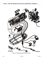
Страница 244: ...SECTION 7 BASIC TROUBLESHOOTING ELECTRICAL INFORMATION SCHEMATICS 7 30 JLG Lift 3121827 Figure 7 18 Electrical Components Installation Sheet 1...

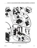
Страница 245: ...SECTION 7 BASIC TROUBLESHOOTING ELECTRICAL INFORMATION SCHEMATICS 3121827 JLG Lift 7 31 Figure 7 19 Electrical Components Installation Sheet 2...

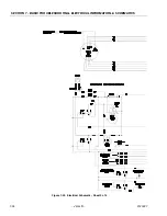
Страница 246: ...SECTION 7 BASIC TROUBLESHOOTING ELECTRICAL INFORMATION SCHEMATICS 7 32 JLG Lift 3121827 Figure 7 20 Electrical Schematic Sheet 1 of 4...

Страница 247: ...SECTION 7 BASIC TROUBLESHOOTING ELECTRICAL INFORMATION SCHEMATICS 3121827 JLG Lift 7 33 Figure 7 21 Electrical Schematic Sheet 2 of 4 1870227 B...

Страница 248: ...SECTION 7 BASIC TROUBLESHOOTING ELECTRICAL INFORMATION SCHEMATICS 7 34 JLG Lift 3121827 Figure 7 22 Electrical Schematic Sheet 3 of 4...

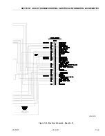
Страница 249: ...SECTION 7 BASIC TROUBLESHOOTING ELECTRICAL INFORMATION SCHEMATICS 3121827 JLG Lift 7 35 Figure 7 23 Electrical Schematic Sheet 4 of 4 1870227 B...

Страница 250: ...SECTION 7 BASIC TROUBLESHOOTING ELECTRICAL INFORMATION SCHEMATICS 7 36 JLG Lift 3121827 Figure 7 24 Hydraulic Schematic M400A E400A Sheet 1 of 2...

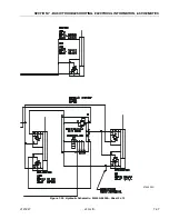
Страница 251: ...SECTION 7 BASIC TROUBLESHOOTING ELECTRICAL INFORMATION SCHEMATICS 3121827 JLG Lift 7 37 2792505D Figure 7 25 Hydraulic Schematic M400A E400A Sheet 2 of 2...

Страница 252: ...SECTION 7 BASIC TROUBLESHOOTING ELECTRICAL INFORMATION SCHEMATICS 7 38 JLG Lift 3121827 Figure 7 26 Hydraulic Schematic M400AJ E400AJ Sheet 1 of 2...

Страница 253: ...SECTION 7 BASIC TROUBLESHOOTING ELECTRICAL INFORMATION SCHEMATICS 3121827 JLG Lift 7 39 2792505D Figure 7 27 Hydraulic Schematic M400AJ E400AJ Sheet 2 of 2...

Страница 254: ...SECTION 7 BASIC TROUBLESHOOTING ELECTRICAL INFORMATION SCHEMATICS 7 40 JLG Lift 3121827 Figure 7 28 Hydraulic Schematic M400AJ E400AJ Sheet 1 of 2...

Страница 255: ...SECTION 7 BASIC TROUBLESHOOTING ELECTRICAL INFORMATION SCHEMATICS 3121827 JLG Lift 7 41 2792505D Figure 7 29 Hydraulic Schematic M400AJP E400AJP Sheet 2 of 2...

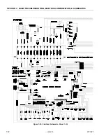
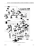
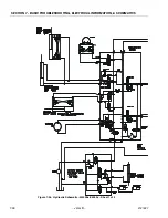
Страница 256: ...SECTION 7 BASIC TROUBLESHOOTING ELECTRICAL INFORMATION SCHEMATICS 7 42 JLG Lift 3121827 Figure 7 30 Hydraulic Schematic Component List...

Страница 257: ......
Страница 258: ...let France 33 0 5 53 88 31 70 33 0 5 53 88 31 79 JLG Deutschland GmbH Max Planck Str 21 D 27721 Ritterhude Ihlpohl Germany 49 0 421 69 350 20 49 0 421 69 350 45 JLG Equipment Services Ltd Rm 1107 Land...

Отзывы: