SECTION 3 - CHASSIS & TURNTABLE
3-54
– JLG Lift –
3121827
3.12 GENERATOR (PRIOR TO S/N 88539)
NOTE:
Throughout the Generator section, the abbreviations
RBS and CTS are used. RBS stands for Rotary Bat-
tery System, which is the generator system. CTS
stands for Call To Start, which is the electronic inputs
which signal the generator to start and charge the
batteries.
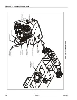
The generator consists of a drive engine, controller, and
related components.
Alternator
The alternator is a brushless, DC output alternator. The 3
phase output of the alternator is full wave rectified and
directed to the output terminator.
The output rating is 58 volts DC at 45 amps. Voltage regu-
lation and current limiting is provided by the Engine/Gen-
erator Controller.
The rectifier diodes and output current sensor are located
in the alternator end.
Dynamo and Dynamo Voltage Regulator
The engine is equipped with a 12 Volt, 15 Amp DC output
dynamo.
Dynamo Output Fuse
The dynamo output fuse is used to protect the output of
the dynamo. This fuse is rated at 20 Amps DC, slow blow
and is located on the left side of the engine.
Control Fuse
This fuse provides power to the engine/generator and the
relays for start control, fuel control, and pre-heater. This
fuse is rated at 15 Amps DC and is located on the right
side of the engine.
Start Battery
A 12 volt lead-acid battery is utilized to provide starting
power for the generator and power for the generator con-
trols. This battery is charged by the engine dynamo and
dynamo regulator when the engine is running.
Engine Starter
The engine is equipped with a 12 Volt DC starter. This
starter provides mechanical power to crank the engine.
Electrical power for the starter is provided by the start bat-
tery. The starter is energized by the start control relay.
Start Control Relay
The start control relay energizes the solenoid of the
engine starter and the pull coil of the engine fuel solenoid.
The start control relay is located on the fuel solenoid
bracket on the right side of the engine. The start control
relay is energized by the engine/generator controller.
Fuel Control Relay
The fuel control relay energizes the hold coil of the fuel
solenoid. The fuel control relay is energized by the
engine/generator controller.
Fuel Solenoid
The fuel solenoid actuates the run/stop lever of the
engine. This solenoid has a pull and hold coil. The pull coil
is energized by the start control relay and the hold coil is
energized by the fuel control relay.
Engine Oil Temperature Sensor
The engine oil temperature sensor is used to sense the
temperature of the oil in the sump of the engine. This sen-
sor provides a signal to the engine/generator controller for
high engine temperature shutdown.
Alternator Output Current Sensor
The alternator output current sensor provides a signal pro-
portional to the output current of the alternator to the
engine/generator controller. This signal is used by the
controller to regulate the current output of the alternator.
The output current is regulated at 55 Amps DC. The alter-
nator output current sensor is located inside the rear
cover of the alternator.
Engine Speed Sensor
The engine speed sensor provides a signal proportional
to the rotational speed of the engine to the engine/genera-
tor controller. This signal is used by the controller to deter-
mine starter cut-out, overspeed fault, and underspeed
fault. This signal has fail-safe protection, if it is not present
at the controller, the unit will fault with a loss of speed sig-
nal indication. The engine speed sensor is located inside
the recoil starter cover at the front of the engine.
Engine Low Oil Pressure Switch
The engine is equipped with a low oil pressure switch. The
switch is closed when the oil pressure is below 14.2 psi (1
Bar)
Timing Sequences
• RBS Pre-start Sequence
1.
Time Delay Engine Start (TDES)
TDES is the period which the RBS waits to verify that
the CTS is valid rather than a transient condition.
Содержание JLG E400AJP
Страница 2: ......
Страница 21: ...SECTION 1 SPECIFICATIONS 3121827 JLG Lift 1 7 Figure 1 2 Operator Maintenance Lubrication Diagram...
Страница 32: ...SECTION 1 SPECIFICATIONS 1 18 JLG Lift 3121827 NOTES...
Страница 42: ...SECTION 2 GENERAL 2 10 JLG Lift 3121827 NOTES...
Страница 54: ...SECTION 3 CHASSIS TURNTABLE 3 12 JLG Lift 3121827 Figure 3 3 Speed Sensor Orientation...
Страница 55: ...SECTION 3 CHASSIS TURNTABLE 3121827 JLG Lift 3 13 Figure 3 4 Frame Mounted Electrical Components Sheet 1 of 2...
Страница 56: ...SECTION 3 CHASSIS TURNTABLE 3 14 JLG Lift 3121827 Figure 3 5 Frame Mounted Electrical Components Sheet 2 of 2...
Страница 60: ...SECTION 3 CHASSIS TURNTABLE 3 18 JLG Lift 3121827 Figure 3 7 Steering Components and Spindles...
Страница 62: ...SECTION 3 CHASSIS TURNTABLE 3 20 JLG Lift 3121827 Figure 3 9 Tilt Sensor Location...
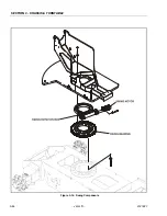
Страница 86: ...SECTION 3 CHASSIS TURNTABLE 3 44 JLG Lift 3121827 Figure 3 16 Swing Components...
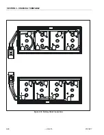
Страница 88: ...SECTION 3 CHASSIS TURNTABLE 3 46 JLG Lift 3121827 Figure 3 18 Battery Cable Connections...
Страница 90: ...SECTION 3 CHASSIS TURNTABLE 3 48 JLG Lift 3121827 Figure 3 20 On Board Generator...
Страница 97: ...SECTION 3 CHASSIS TURNTABLE 3121827 JLG Lift 3 55 Figure 3 22 Generator Components...
Страница 100: ...SECTION 3 CHASSIS TURNTABLE 3 58 JLG Lift 3121827 Figure 3 23 Generator System Analyzer Flow Chart...
Страница 116: ...SECTION 3 CHASSIS TURNTABLE 3 74 JLG Lift 3121827 NOTES...
Страница 125: ...SECTION 4 BOOM PLATFORM 3121827 JLG Lift 4 9 Figure 4 8 Jib Platform Components and Attaching Hardware...
Страница 127: ...SECTION 4 BOOM PLATFORM 3121827 JLG Lift 4 11 Figure 4 10 Boom Limit Switches...
Страница 140: ...SECTION 4 BOOM PLATFORM 4 24 JLG Lift 3121827 Figure 4 13 Rotator Counterbalance Valve...
Страница 178: ...SECTION 5 HYDRAULICS 5 24 JLG Lift 3121827 Figure 5 26 HydraForce Cartridge Torque Value Chart...
Страница 179: ...SECTION 5 HYDRAULICS 3121827 JLG Lift 5 25 Figure 5 27 Main Valve Components Prior to S N 62642...
Страница 214: ...SECTION 6 JLG CONTROL SYSTEM 6 34 JLG Lift 3121827 NOTES...
Страница 257: ......

