SECTION 4 - BOOM & PLATFORM
4-6
– JLG Lift –
3121827
4.5 UPPER BOOM TELESCOPE CYLINDER
Removal
1.
Place machine on flat and level surface, with Upper
Boom in the horizontal position. Extend Upper
Boom until fly attach pin #1 is accessible on fly.
2.
Support Upper Boom basket end with a prop. Sup-
port Upper Upright end with an overhead crane.
3.
Tag, disconnect hydraulic lines to telescope cylinder.
Use suitable container to retain any residual hydrau-
lic fluid. Cap hydraulic lines and ports.
4.
Remove the retaining rings that retain the telescope
cylinder rod to the fly boom.
5.
Using a suitable brass drift, carefully drive the tele-
scope cylinder rod pin #1 from the fly boom.
6.
Remove the four (4) bolts securing the telescope
cylinder barrel end to the base boom.
NOTE:
Care should be taken when removing the telescope
cylinder, do not leave cylinder rest on power track
which could cause damage to power track.
7.
Using a suitable brass drift, carefully drive the tele-
scope cylinder pin from the base boom.
8.
Attach a suitable sling to the telescope cylinder.
Using a suitable lifting device attached to the sling
carefully pull the telescope cylinder from the boom
assembly.
9.
Using another lifting device, support the rod end of
the cylinder and remove the cylinder from the boom
assembly.
10.
Carefully lift the cylinder clear of the boom assembly
and lower to the ground or suitably supported work
area.
Installation
1.
Attach a hydraulic power supply to the telescope
cylinder ports. Using suitable supports or lifting
devices at each end of the cylinder, extend the rod
so that the cylinder pin attach holes are the same
distance apart as the boom pin attach holes.
2.
Using suitable lifting equipment, carefully lower the
cylinder to the boom assembly.
3.
Using another lifting device, support the rod end of
the cylinder and install the cylinder into the boom
assembly.
4.
Remove lifting devices from the telescope cylinder.
5.
Carefully install the telescope cylinder rod pin #1
through the fly boom and secure it with the retaining
rings.
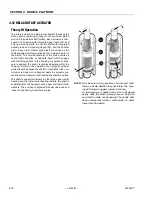
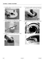
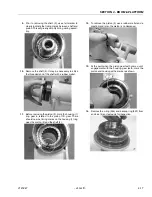
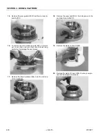
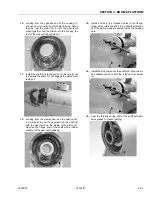
Figure 4-5. Upper Telescope Cylinder Removal
Содержание JLG E400AJP
Страница 2: ......
Страница 21: ...SECTION 1 SPECIFICATIONS 3121827 JLG Lift 1 7 Figure 1 2 Operator Maintenance Lubrication Diagram...
Страница 32: ...SECTION 1 SPECIFICATIONS 1 18 JLG Lift 3121827 NOTES...
Страница 42: ...SECTION 2 GENERAL 2 10 JLG Lift 3121827 NOTES...
Страница 54: ...SECTION 3 CHASSIS TURNTABLE 3 12 JLG Lift 3121827 Figure 3 3 Speed Sensor Orientation...
Страница 55: ...SECTION 3 CHASSIS TURNTABLE 3121827 JLG Lift 3 13 Figure 3 4 Frame Mounted Electrical Components Sheet 1 of 2...
Страница 56: ...SECTION 3 CHASSIS TURNTABLE 3 14 JLG Lift 3121827 Figure 3 5 Frame Mounted Electrical Components Sheet 2 of 2...
Страница 60: ...SECTION 3 CHASSIS TURNTABLE 3 18 JLG Lift 3121827 Figure 3 7 Steering Components and Spindles...
Страница 62: ...SECTION 3 CHASSIS TURNTABLE 3 20 JLG Lift 3121827 Figure 3 9 Tilt Sensor Location...
Страница 86: ...SECTION 3 CHASSIS TURNTABLE 3 44 JLG Lift 3121827 Figure 3 16 Swing Components...
Страница 88: ...SECTION 3 CHASSIS TURNTABLE 3 46 JLG Lift 3121827 Figure 3 18 Battery Cable Connections...
Страница 90: ...SECTION 3 CHASSIS TURNTABLE 3 48 JLG Lift 3121827 Figure 3 20 On Board Generator...
Страница 97: ...SECTION 3 CHASSIS TURNTABLE 3121827 JLG Lift 3 55 Figure 3 22 Generator Components...
Страница 100: ...SECTION 3 CHASSIS TURNTABLE 3 58 JLG Lift 3121827 Figure 3 23 Generator System Analyzer Flow Chart...
Страница 116: ...SECTION 3 CHASSIS TURNTABLE 3 74 JLG Lift 3121827 NOTES...
Страница 125: ...SECTION 4 BOOM PLATFORM 3121827 JLG Lift 4 9 Figure 4 8 Jib Platform Components and Attaching Hardware...
Страница 127: ...SECTION 4 BOOM PLATFORM 3121827 JLG Lift 4 11 Figure 4 10 Boom Limit Switches...
Страница 140: ...SECTION 4 BOOM PLATFORM 4 24 JLG Lift 3121827 Figure 4 13 Rotator Counterbalance Valve...
Страница 178: ...SECTION 5 HYDRAULICS 5 24 JLG Lift 3121827 Figure 5 26 HydraForce Cartridge Torque Value Chart...
Страница 179: ...SECTION 5 HYDRAULICS 3121827 JLG Lift 5 25 Figure 5 27 Main Valve Components Prior to S N 62642...
Страница 214: ...SECTION 6 JLG CONTROL SYSTEM 6 34 JLG Lift 3121827 NOTES...
Страница 257: ......


