SECTION 3 - CHASSIS & TURNTABLE
3121827
– JLG Lift –
3-53
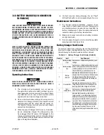
Checking/Changing the Battery Charger
Algorithm
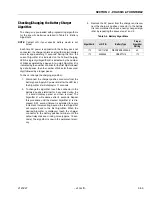
The charger is pre-loaded with programming algorithms
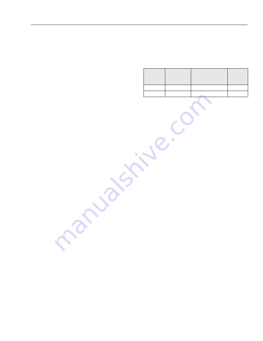
for the specific batteries detailed in Table 3-4, Battery
Algorithms.
NOTE:
Contact JLG if your specific battery model is not
listed.
Each time AC power is applied with the battery pack not
connected, the charger enters an algorithm select/display
mode for approximately 11 seconds. During this time, the
current Algorithm # is indicated on the Yellow Charging
LED. A single digit Algorithm # is indicated by the number
of blinks separated by a pause. A two digit Algorithm # is
indicated by the number of blinks for the first digit followed
by a short pause, then the number of blinks for the second
digit followed by a longer pause.
To check / change the charging algorithm:
1. Disconnect the charger positive connector from the
battery pack. Apply AC power and after the LED test,
the Algorithm # will display for 11 seconds.
2. To change the algorithm, touch the connector to the
battery’s positive terminal for 3 seconds during the
11 second display period and then remove. The
Algorithm # will advance after 3 seconds. Repeat
this procedure until the desired Algorithm # is dis-
played. A 30 second timeout is extended for every
increment. Incrementing beyond the last Algorithm
will recycle back to the first Algorithm. When the
desired Algorithm is displayed, touch the charger
connector to the battery positive terminal until the
output relay makes a clicking noise (approx. 10 sec-
onds). The algorithm is now in the permanent mem-
ory.
3. Remove the AC power from the charger and recon-
nect the charger’s positive connector to the battery.
It is recommended to check a newly changed algo-
rithm by repeating the above steps 1 and 3.
Table 3-4. Battery Algorithms
Algorithm #
JLG P/N
Battery Type
Proper
Algorithm
Setting
173
1001114782
DISCOVER EV 305A-A
43
173
0400055
US BATT L16
173
Содержание JLG E400AJP
Страница 2: ......
Страница 21: ...SECTION 1 SPECIFICATIONS 3121827 JLG Lift 1 7 Figure 1 2 Operator Maintenance Lubrication Diagram...
Страница 32: ...SECTION 1 SPECIFICATIONS 1 18 JLG Lift 3121827 NOTES...
Страница 42: ...SECTION 2 GENERAL 2 10 JLG Lift 3121827 NOTES...
Страница 54: ...SECTION 3 CHASSIS TURNTABLE 3 12 JLG Lift 3121827 Figure 3 3 Speed Sensor Orientation...
Страница 55: ...SECTION 3 CHASSIS TURNTABLE 3121827 JLG Lift 3 13 Figure 3 4 Frame Mounted Electrical Components Sheet 1 of 2...
Страница 56: ...SECTION 3 CHASSIS TURNTABLE 3 14 JLG Lift 3121827 Figure 3 5 Frame Mounted Electrical Components Sheet 2 of 2...
Страница 60: ...SECTION 3 CHASSIS TURNTABLE 3 18 JLG Lift 3121827 Figure 3 7 Steering Components and Spindles...
Страница 62: ...SECTION 3 CHASSIS TURNTABLE 3 20 JLG Lift 3121827 Figure 3 9 Tilt Sensor Location...
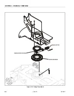
Страница 86: ...SECTION 3 CHASSIS TURNTABLE 3 44 JLG Lift 3121827 Figure 3 16 Swing Components...
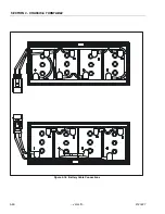
Страница 88: ...SECTION 3 CHASSIS TURNTABLE 3 46 JLG Lift 3121827 Figure 3 18 Battery Cable Connections...
Страница 90: ...SECTION 3 CHASSIS TURNTABLE 3 48 JLG Lift 3121827 Figure 3 20 On Board Generator...
Страница 97: ...SECTION 3 CHASSIS TURNTABLE 3121827 JLG Lift 3 55 Figure 3 22 Generator Components...
Страница 100: ...SECTION 3 CHASSIS TURNTABLE 3 58 JLG Lift 3121827 Figure 3 23 Generator System Analyzer Flow Chart...
Страница 116: ...SECTION 3 CHASSIS TURNTABLE 3 74 JLG Lift 3121827 NOTES...
Страница 125: ...SECTION 4 BOOM PLATFORM 3121827 JLG Lift 4 9 Figure 4 8 Jib Platform Components and Attaching Hardware...
Страница 127: ...SECTION 4 BOOM PLATFORM 3121827 JLG Lift 4 11 Figure 4 10 Boom Limit Switches...
Страница 140: ...SECTION 4 BOOM PLATFORM 4 24 JLG Lift 3121827 Figure 4 13 Rotator Counterbalance Valve...
Страница 178: ...SECTION 5 HYDRAULICS 5 24 JLG Lift 3121827 Figure 5 26 HydraForce Cartridge Torque Value Chart...
Страница 179: ...SECTION 5 HYDRAULICS 3121827 JLG Lift 5 25 Figure 5 27 Main Valve Components Prior to S N 62642...
Страница 214: ...SECTION 6 JLG CONTROL SYSTEM 6 34 JLG Lift 3121827 NOTES...
Страница 257: ......

