SECTION 3 - CHASSIS & TURNTABLE
3121827
– JLG Lift –
3-49
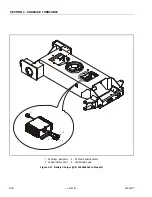
3.10 BATTERY CHARGER (S/N 0300059350
TO PRESENT)
LEAD ACID BATTERIES MAY GENERATE EXPLOSIVE HYDROGEN
GAS DURING NORMAL OPERATION. KEEP SPARKS, FLAMES,
AND SMOKING MATERIALS AWAY FROM BATTERIES. PROVIDE
ADEQUATE VENTILATION DURING CHARGING. NEVER CHARGE A
FROZEN BATTERY. STUDY ALL BATTERY MANUFACTURERS'
SPECIFIC PRECAUTIONS SUCH AS RECOMMENDED RATES OF
CHARGE AND REMOVING OR NOT REMOVING CELL CAPS WHILE
CHARGING.
RISK OF ELECTRIC SHOCK. CONNECT CHARGER POWER CORD
TO AN OUTLET THAT HAS BEEN PROPERLY INSTALLED AND
GROUNDED IN ACCORDANCE WITH ALL LOCAL CODES AND
ORDINANCES. A GROUNDED OUTLET IS REQUIRED TO REDUCE
RISK OF ELECTRIC SHOCK - DO NOT USE GROUND ADAPTERS
OR MODIFY PLUG. DO NOT TOUCH UNINSULATED PORTION OF
OUTPUT CONNECTOR OR UNINSULATED BATTERY TERMINAL.
DISCONNECT THE AC SUPPLY BEFORE MAKING OR BREAKING
THE CONNECTIONS TO THE BATTERY WHILE CHARGING. DO NOT
OPEN OR DISASSEMBLE CHARGER. DO NOT OPERATE CHARGER
IF THE AC SUPPLY CORD IS DAMAGED OR IF THE CHARGER HAS
RECEIVED A SHARP BLOW, BEEN DROPPED, OR OTHERWISE
DAMAGED IN ANY WAY - REFER ALL REPAIR WORK TO QUALI-
FIED PERSONNEL. NOT FOR USE BY CHILDREN.
Operating Instructions
ALWAYS USE A GROUNDED OUTLET. WHEN USING AN EXTEN-
SION CORD, AVOID EXCESSIVE VOLTAGE DROPS BY USING A
GROUNDED 3-WIRE 12 AWG CORD.
1.
The charger will automatically turn on and go
through a short self-test. All LED’s will flash in an up-
down sequence for two seconds. The yellow "Charg-
ing" LED will turn on and a trickle current will be
applied until a minimum voltage is reached.
2.
Once a minimum battery voltage of 2 volts per cell is
detected, the charger will enter the constant-current
charging stage and the yellow LED will remain on.
The length of charge time will vary by input voltage
and ambient temperature.
3.
When the green "Charged" LED turns on, the batter-
ies are completely charged. The charger may now
be unplugged from AC power. If left plugged in, the
charger will automatically restart a complete charge
cycle if battery voltage drops below a minimum volt-
age or 30 days have elapsed.
4.
If a fault occurred during charging, the red "Fault"
LED will flash with a code corresponding to the error.
Maintenance Instructions
1.
For flooded lead-acid batteries, regularly check
water levels of each battery cell after charging and
add distilled water as required to level specified by
battery manufacturer. Follow the safety instructions
recommended by the battery manufacturer.
2.
Make sure charger connections to battery terminals
are tight and clean.
3.
Do not expose charger to oil or to direct heavy water
spraying when cleaning vehicle.
Battery Charger Fault Codes
If a fault occurred during charging, the red "Fault" LED will
flash with a code corresponding to the error. Refer to the
table following for the flash codes and their removal.
Table 3-11. Battery Charger Fault Codes (Delta-Q)
Flash(s)
Fault
Fault Removal
1
Battery voltage
high
Auto-recover - Indicates a high battery pack
voltage
2
Battery voltage
low
Auto-recover - Indicates either a battery pack
failure, battery pack not connected to charger
or battery volts per cell is less than 0.5 VDC.
Check the battery pack and connections
3
Charge
time-out
Indicates the batteries did not charge in the
allowed time. This could occur if the batteries
are a larger capacity than the algorithm is
intended for or if the batteries are damaged
old or in poor condition.
4
Check battery
Indicates the batteries could not be trickle
charged up to the minimum voltage per cell
level required for the charge to be started.
5
Over-
temperature
Auto-recover - Indicates charger has shut
down due to high internal temperature
6
QuiQ fault
Indicates that the battery will not accept
charge current, or an internal fault has been
detected in the charger. This fault will nearly
always be set within the first 30 seconds of
operation. Once it has been determined that
the batteries and connections are not faulty
and fault 6 is again displayed after interrupt-
ing AC power for at least 10 seconds, the
charger must be brought to a qualified service
depot.
Содержание JLG E400AJP
Страница 2: ......
Страница 21: ...SECTION 1 SPECIFICATIONS 3121827 JLG Lift 1 7 Figure 1 2 Operator Maintenance Lubrication Diagram...
Страница 32: ...SECTION 1 SPECIFICATIONS 1 18 JLG Lift 3121827 NOTES...
Страница 42: ...SECTION 2 GENERAL 2 10 JLG Lift 3121827 NOTES...
Страница 54: ...SECTION 3 CHASSIS TURNTABLE 3 12 JLG Lift 3121827 Figure 3 3 Speed Sensor Orientation...
Страница 55: ...SECTION 3 CHASSIS TURNTABLE 3121827 JLG Lift 3 13 Figure 3 4 Frame Mounted Electrical Components Sheet 1 of 2...
Страница 56: ...SECTION 3 CHASSIS TURNTABLE 3 14 JLG Lift 3121827 Figure 3 5 Frame Mounted Electrical Components Sheet 2 of 2...
Страница 60: ...SECTION 3 CHASSIS TURNTABLE 3 18 JLG Lift 3121827 Figure 3 7 Steering Components and Spindles...
Страница 62: ...SECTION 3 CHASSIS TURNTABLE 3 20 JLG Lift 3121827 Figure 3 9 Tilt Sensor Location...
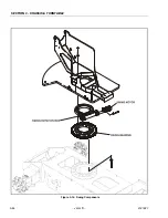
Страница 86: ...SECTION 3 CHASSIS TURNTABLE 3 44 JLG Lift 3121827 Figure 3 16 Swing Components...
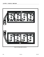
Страница 88: ...SECTION 3 CHASSIS TURNTABLE 3 46 JLG Lift 3121827 Figure 3 18 Battery Cable Connections...
Страница 90: ...SECTION 3 CHASSIS TURNTABLE 3 48 JLG Lift 3121827 Figure 3 20 On Board Generator...
Страница 97: ...SECTION 3 CHASSIS TURNTABLE 3121827 JLG Lift 3 55 Figure 3 22 Generator Components...
Страница 100: ...SECTION 3 CHASSIS TURNTABLE 3 58 JLG Lift 3121827 Figure 3 23 Generator System Analyzer Flow Chart...
Страница 116: ...SECTION 3 CHASSIS TURNTABLE 3 74 JLG Lift 3121827 NOTES...
Страница 125: ...SECTION 4 BOOM PLATFORM 3121827 JLG Lift 4 9 Figure 4 8 Jib Platform Components and Attaching Hardware...
Страница 127: ...SECTION 4 BOOM PLATFORM 3121827 JLG Lift 4 11 Figure 4 10 Boom Limit Switches...
Страница 140: ...SECTION 4 BOOM PLATFORM 4 24 JLG Lift 3121827 Figure 4 13 Rotator Counterbalance Valve...
Страница 178: ...SECTION 5 HYDRAULICS 5 24 JLG Lift 3121827 Figure 5 26 HydraForce Cartridge Torque Value Chart...
Страница 179: ...SECTION 5 HYDRAULICS 3121827 JLG Lift 5 25 Figure 5 27 Main Valve Components Prior to S N 62642...
Страница 214: ...SECTION 6 JLG CONTROL SYSTEM 6 34 JLG Lift 3121827 NOTES...
Страница 257: ......

