SECTION 7 - BASIC TROUBLESHOOTING, ELECTRICAL INFORMATION, & SCHEMATICS
3121827
– JLG Lift –
7-7
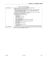
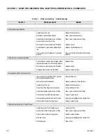
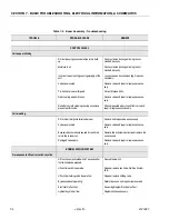
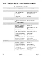
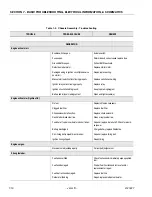
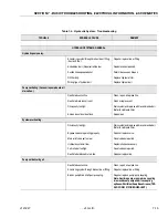
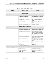
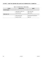
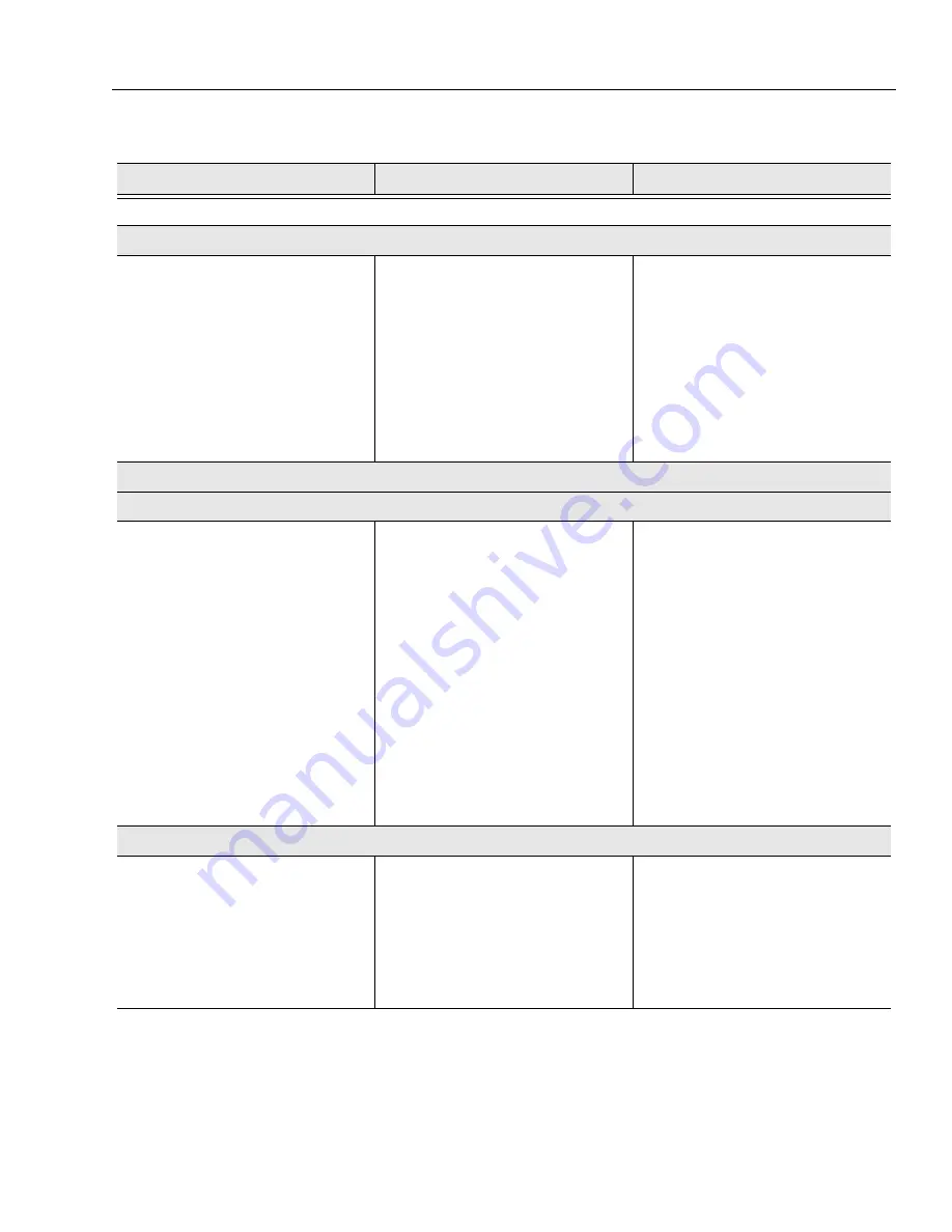
Boom extends and retracts erratically.
Hydraulic system oil low.
Replenish oil as necessary.
Wear pads worn.
Replace pads as required.
Restricted or broken hydraulic line or fitting.
Clean, repair, or replace line or fitting.
Directional valve not functioning properly.
Repair or replace valve.
Worn seals in telescope cylinder.
Replace seals.
Cylinder not functioning properly.
Repair or replace cylinder.
Counterbalance valve not functioning properly.
Replace counterbalance valve.
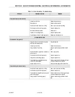
BOOM SWING SYSTEM
No response to swing control.
Swing function not activated within 7 seconds
after footswitch was depressed.
Recycle footswitch.
Hydraulic system oil low.
Replenish oil as necessary.
Swing Joystick not functioning.
Repair or replace swing joystick/Run System
Test.
Restricted or broken supply line on valve bank or
hydraulic pump.
Clean or replace line.
Directional valve not functioning properly.
Repair or replace valve.
Swing motor not functioning properly.
Repair or replace motor.
Foreign objects(s) wedged between swing
motor pinion and swing gear.
Remove objects, check for damage, and repair
or replace component(s) as required.
No electric power to valve.
See proper wiring diagram/Run System Test.
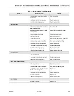
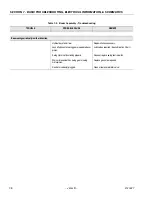
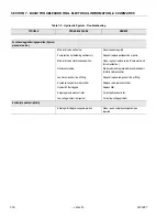
Boom will swing in one direction only.
Restricted or broken hydraulic line or fitting.
Clean, repair, or replace line or fitting.
Directional valve not functioning properly.
Repair or replace valve.
Foreign object(s) wedged between swing motor
pinion and swing gear.
Remove object(s), check for damage and repair
or replace component(s) as required.
Swing Joystick not functioning properly.
Repair or replace swing joystick/Run System
Test.
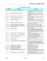
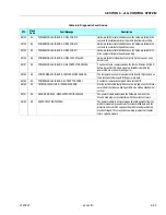
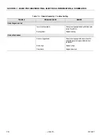
Table 7-2. Boom Assembly - Troubleshooting
TROUBLE
PROBABLE CAUSE
REMEDY
Содержание JLG E400AJP
Страница 2: ......
Страница 21: ...SECTION 1 SPECIFICATIONS 3121827 JLG Lift 1 7 Figure 1 2 Operator Maintenance Lubrication Diagram...
Страница 32: ...SECTION 1 SPECIFICATIONS 1 18 JLG Lift 3121827 NOTES...
Страница 42: ...SECTION 2 GENERAL 2 10 JLG Lift 3121827 NOTES...
Страница 54: ...SECTION 3 CHASSIS TURNTABLE 3 12 JLG Lift 3121827 Figure 3 3 Speed Sensor Orientation...
Страница 55: ...SECTION 3 CHASSIS TURNTABLE 3121827 JLG Lift 3 13 Figure 3 4 Frame Mounted Electrical Components Sheet 1 of 2...
Страница 56: ...SECTION 3 CHASSIS TURNTABLE 3 14 JLG Lift 3121827 Figure 3 5 Frame Mounted Electrical Components Sheet 2 of 2...
Страница 60: ...SECTION 3 CHASSIS TURNTABLE 3 18 JLG Lift 3121827 Figure 3 7 Steering Components and Spindles...
Страница 62: ...SECTION 3 CHASSIS TURNTABLE 3 20 JLG Lift 3121827 Figure 3 9 Tilt Sensor Location...
Страница 86: ...SECTION 3 CHASSIS TURNTABLE 3 44 JLG Lift 3121827 Figure 3 16 Swing Components...
Страница 88: ...SECTION 3 CHASSIS TURNTABLE 3 46 JLG Lift 3121827 Figure 3 18 Battery Cable Connections...
Страница 90: ...SECTION 3 CHASSIS TURNTABLE 3 48 JLG Lift 3121827 Figure 3 20 On Board Generator...
Страница 97: ...SECTION 3 CHASSIS TURNTABLE 3121827 JLG Lift 3 55 Figure 3 22 Generator Components...
Страница 100: ...SECTION 3 CHASSIS TURNTABLE 3 58 JLG Lift 3121827 Figure 3 23 Generator System Analyzer Flow Chart...
Страница 116: ...SECTION 3 CHASSIS TURNTABLE 3 74 JLG Lift 3121827 NOTES...
Страница 125: ...SECTION 4 BOOM PLATFORM 3121827 JLG Lift 4 9 Figure 4 8 Jib Platform Components and Attaching Hardware...
Страница 127: ...SECTION 4 BOOM PLATFORM 3121827 JLG Lift 4 11 Figure 4 10 Boom Limit Switches...
Страница 140: ...SECTION 4 BOOM PLATFORM 4 24 JLG Lift 3121827 Figure 4 13 Rotator Counterbalance Valve...
Страница 178: ...SECTION 5 HYDRAULICS 5 24 JLG Lift 3121827 Figure 5 26 HydraForce Cartridge Torque Value Chart...
Страница 179: ...SECTION 5 HYDRAULICS 3121827 JLG Lift 5 25 Figure 5 27 Main Valve Components Prior to S N 62642...
Страница 214: ...SECTION 6 JLG CONTROL SYSTEM 6 34 JLG Lift 3121827 NOTES...
Страница 257: ......

