SECTION 3 - CHASSIS & TURNTABLE
3121827
– JLG Lift –
3-45
3.9 BATTERY MAINTENANCE AND
CHARGING
Battery Maintenance, Quarterly
1.
Open battery compartment cover to allow access to
battery terminals and vent caps.
WHEN ADDING WATER TO BATTERIES, ADD WATER UNTIL ELEC-
TROLYTE COVERS PLATES. DO NOT CHARGE BATTERIES UNLESS
ELECTROLYTE COVERS THE PLATES.
NOTE:
When adding distilled water to batteries, non-metallic
containers and/or funnels must be used.
To avoid electrolyte overflow, add distilled water to
batteries after charging.
When adding water to the battery, fill only to level
indicated or 3/8”(1 cm) above separators.
2.
Remove all vent caps and inspect electrolyte level of
each cell. Electrolyte level should be to the ring
approximately one inch from top of battery. Fill bat-
teries with distilled water only. Replace and secure
all vent caps.
3.
Remove battery cables from each battery post one
at a time, negative first. Clean cables with acid neu-
tralizing solution (e.g. baking soda and water or
ammonia) and wire brush. Replace cables and/or
cable clamp bolts as required.
4.
Clean battery post with wire brush then re-connect
cable to post. Coat non-contact surfaces with min-
eral grease or petroleum jelly.
5.
When all cables and terminal posts have been
cleaned, ensure all cables are properly positioned
and do not get pinched. Close battery compartment
cover.
6.
Start hydraulic system and ensure that it functions
properly.
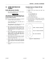
Charging Sequence of Remote LED Card
1.
Plug in charger.
2.
All three LED’s (light emitting diode) flash three
times.
3.
In sequence.
a.
Green LED flashes once.
b.
Yellow LED flashes once.
c.
Red LED flashes once.
4.
All Three LED flash three times.
5.
Yellow LED comes on indicates charger is charging.
6.
Yellow LED will stay on until fully charged and green
LED will illuminate.
7.
If Red LED remains on, this indicates a fault.
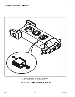
Figure 3-17. Remote LED Card
Содержание JLG E400AJP
Страница 2: ......
Страница 21: ...SECTION 1 SPECIFICATIONS 3121827 JLG Lift 1 7 Figure 1 2 Operator Maintenance Lubrication Diagram...
Страница 32: ...SECTION 1 SPECIFICATIONS 1 18 JLG Lift 3121827 NOTES...
Страница 42: ...SECTION 2 GENERAL 2 10 JLG Lift 3121827 NOTES...
Страница 54: ...SECTION 3 CHASSIS TURNTABLE 3 12 JLG Lift 3121827 Figure 3 3 Speed Sensor Orientation...
Страница 55: ...SECTION 3 CHASSIS TURNTABLE 3121827 JLG Lift 3 13 Figure 3 4 Frame Mounted Electrical Components Sheet 1 of 2...
Страница 56: ...SECTION 3 CHASSIS TURNTABLE 3 14 JLG Lift 3121827 Figure 3 5 Frame Mounted Electrical Components Sheet 2 of 2...
Страница 60: ...SECTION 3 CHASSIS TURNTABLE 3 18 JLG Lift 3121827 Figure 3 7 Steering Components and Spindles...
Страница 62: ...SECTION 3 CHASSIS TURNTABLE 3 20 JLG Lift 3121827 Figure 3 9 Tilt Sensor Location...
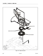
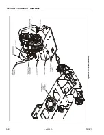
Страница 86: ...SECTION 3 CHASSIS TURNTABLE 3 44 JLG Lift 3121827 Figure 3 16 Swing Components...
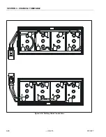
Страница 88: ...SECTION 3 CHASSIS TURNTABLE 3 46 JLG Lift 3121827 Figure 3 18 Battery Cable Connections...
Страница 90: ...SECTION 3 CHASSIS TURNTABLE 3 48 JLG Lift 3121827 Figure 3 20 On Board Generator...
Страница 97: ...SECTION 3 CHASSIS TURNTABLE 3121827 JLG Lift 3 55 Figure 3 22 Generator Components...
Страница 100: ...SECTION 3 CHASSIS TURNTABLE 3 58 JLG Lift 3121827 Figure 3 23 Generator System Analyzer Flow Chart...
Страница 116: ...SECTION 3 CHASSIS TURNTABLE 3 74 JLG Lift 3121827 NOTES...
Страница 125: ...SECTION 4 BOOM PLATFORM 3121827 JLG Lift 4 9 Figure 4 8 Jib Platform Components and Attaching Hardware...
Страница 127: ...SECTION 4 BOOM PLATFORM 3121827 JLG Lift 4 11 Figure 4 10 Boom Limit Switches...
Страница 140: ...SECTION 4 BOOM PLATFORM 4 24 JLG Lift 3121827 Figure 4 13 Rotator Counterbalance Valve...
Страница 178: ...SECTION 5 HYDRAULICS 5 24 JLG Lift 3121827 Figure 5 26 HydraForce Cartridge Torque Value Chart...
Страница 179: ...SECTION 5 HYDRAULICS 3121827 JLG Lift 5 25 Figure 5 27 Main Valve Components Prior to S N 62642...
Страница 214: ...SECTION 6 JLG CONTROL SYSTEM 6 34 JLG Lift 3121827 NOTES...
Страница 257: ......


