SECTION 3 - CHASSIS & TURNTABLE
3-52
– JLG Lift –
3121827
[5 Flashes] - Over Temperature
This fault indicates the charger has become too hot during
operation. Though not damanging to the charger, charge
time will be extended significantly.
1. This fault indication will not clear automatically, but
the charger will restart charging automatically when
the temperature drops. The fault indicaiton must be
cleared manually by unplugging the AC, waiting 30
seconds and reconnecting the AC power.
2. If possible, move the machine to a cooler location.
3. Confirm that dirt or mud is not blocking the cooling
fins of the charger. Clean the charger. Rinse the
charger with a low pressure hose if required. Do no
use high pressure. Do not us a pressure washer.
[6 Flashes] - Over Load/Over Temperature
This fault indicates that the batteries will not accept charge
current, or an internal fault has been detected in the char-
ger. This fault will nearly always be set within the first 30
seconds of operation. If it occurs after the charger has
started charging normally, be sure to make a note of it.
1. Remove excessive AC loads from inverter if
installed.
2. Try to clear the fault by unplugging the AC, waiting
30 seconds and reconnecting the ac power.
3. Check all battery connections. Look for a high resis-
tance connection.The most likely reason for this fault
is a fault in the battery such as a bad battery con-
nection, an open cell, or insufficient water.
4. This fault will occur if an internal fuse inside the char-
ger blows. If the green wire is shorted to ground
even momentarily, this fuse will blow. To check the
fuse, measure with an ohmmeter between the green
and red wires with the AC disconnected. If a short
circuit is not measured, the fuse has blown. Return
unit to a service depot to have this fuse replaced.
5. If this fault occurs after battery charging has started,
confirm that AC power was not interrupted and that
all battery connections are good.
6. If all battery connections are good, an internal fault
has been detected and the charger must be brought
to a qualified service depot.
Excessive Battery Watering Requirements or
Strong Sulphur (Rotten Egg) Smell
These symptoms indicate over-charging or high battery
temperature. These symptoms are unlikely to be caused
by too high a charge current since the maximum charge
current of the charger will be small compared to even a
moderately sized battery pack. The most likely cause for
this problem is incorrect charge algorithm setting and/or
high ambient temperatures.
1. Confirm that the battery pack is not too small - usu-
ally > 50Ah.
2. Confirm that the nominal battery voltage matches
the charger output voltage.
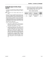
3. Confirm the correct battery charge algorithm. If the
battery pack is new, the algorithm will need to be
changed if the pack is not the same as the old one.
for instructions on how to determine and change the
battery charge algorithm see the following sub-sec-
tion.
4. If the output voltage of the charger seems excessive,
return the charger for service. Contact JLG to get the
expected battery voltage settings for the charger in
question. Be sure to have the charger’s serial num-
ber and charge algorithm setting available when
calling.
Содержание JLG E400AJP
Страница 2: ......
Страница 21: ...SECTION 1 SPECIFICATIONS 3121827 JLG Lift 1 7 Figure 1 2 Operator Maintenance Lubrication Diagram...
Страница 32: ...SECTION 1 SPECIFICATIONS 1 18 JLG Lift 3121827 NOTES...
Страница 42: ...SECTION 2 GENERAL 2 10 JLG Lift 3121827 NOTES...
Страница 54: ...SECTION 3 CHASSIS TURNTABLE 3 12 JLG Lift 3121827 Figure 3 3 Speed Sensor Orientation...
Страница 55: ...SECTION 3 CHASSIS TURNTABLE 3121827 JLG Lift 3 13 Figure 3 4 Frame Mounted Electrical Components Sheet 1 of 2...
Страница 56: ...SECTION 3 CHASSIS TURNTABLE 3 14 JLG Lift 3121827 Figure 3 5 Frame Mounted Electrical Components Sheet 2 of 2...
Страница 60: ...SECTION 3 CHASSIS TURNTABLE 3 18 JLG Lift 3121827 Figure 3 7 Steering Components and Spindles...
Страница 62: ...SECTION 3 CHASSIS TURNTABLE 3 20 JLG Lift 3121827 Figure 3 9 Tilt Sensor Location...
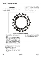
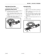
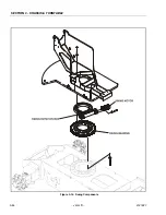
Страница 86: ...SECTION 3 CHASSIS TURNTABLE 3 44 JLG Lift 3121827 Figure 3 16 Swing Components...
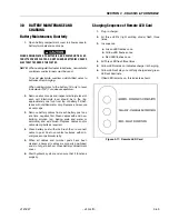
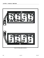
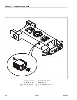
Страница 88: ...SECTION 3 CHASSIS TURNTABLE 3 46 JLG Lift 3121827 Figure 3 18 Battery Cable Connections...
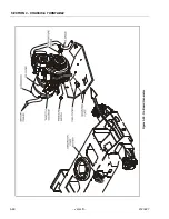
Страница 90: ...SECTION 3 CHASSIS TURNTABLE 3 48 JLG Lift 3121827 Figure 3 20 On Board Generator...
Страница 97: ...SECTION 3 CHASSIS TURNTABLE 3121827 JLG Lift 3 55 Figure 3 22 Generator Components...
Страница 100: ...SECTION 3 CHASSIS TURNTABLE 3 58 JLG Lift 3121827 Figure 3 23 Generator System Analyzer Flow Chart...
Страница 116: ...SECTION 3 CHASSIS TURNTABLE 3 74 JLG Lift 3121827 NOTES...
Страница 125: ...SECTION 4 BOOM PLATFORM 3121827 JLG Lift 4 9 Figure 4 8 Jib Platform Components and Attaching Hardware...
Страница 127: ...SECTION 4 BOOM PLATFORM 3121827 JLG Lift 4 11 Figure 4 10 Boom Limit Switches...
Страница 140: ...SECTION 4 BOOM PLATFORM 4 24 JLG Lift 3121827 Figure 4 13 Rotator Counterbalance Valve...
Страница 178: ...SECTION 5 HYDRAULICS 5 24 JLG Lift 3121827 Figure 5 26 HydraForce Cartridge Torque Value Chart...
Страница 179: ...SECTION 5 HYDRAULICS 3121827 JLG Lift 5 25 Figure 5 27 Main Valve Components Prior to S N 62642...
Страница 214: ...SECTION 6 JLG CONTROL SYSTEM 6 34 JLG Lift 3121827 NOTES...
Страница 257: ......

