SECTION 6 - JLG CONTROL SYSTEM
6-28
– JLG Lift –
3121827
Non
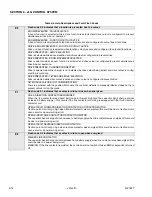
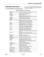
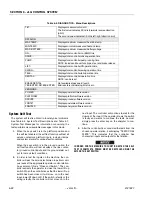
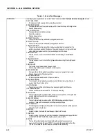
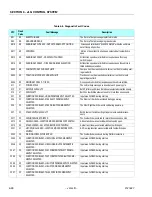
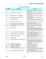
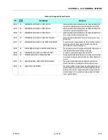
Table 6-8. Diagnostic Fault Codes
DTC
Flash
Code
Fault Message
Description
001
00
EVERYTHING OK
The "normal" help message in platform mode
002
00
GROUND MODE OK
The "normal" help message in ground mode
0010
00
RUNNING AT CUTBACK - OUT OF TRANSPORT POSITION
Drive speed is limited to "ELEVATED MAX" while the vehicle is
out of transport position.
0011
00
FSW OPEN
A drive or boom function has been selected but footswitch is
open.
0012
00
RUNNING AT CREEP - CREEP SWITCH OPEN
All function speeds are limited to creep because the creep
switch is open.
0013
00
RUNNING AT CREEP - TILTED AND ABOVE ELEVATION
All function speeds are limited to creep because the vehicle is
tilted and above elevation.
0032
00
PUMP MOTOR AT CURRENT LIMIT
Pump current has reached controller current limit or safe operat-
ing area limit.
0033
00
TRACTION MOTOR AT CURRENT LIMIT
Traction current has reached controller current limit or safe
operating area limit.
0034
00
DRIVING AT CREEP - TILTED
Drive speed is limited to creep because the vehicle is tilted.
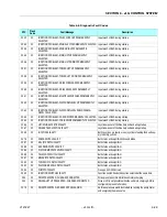
211
21
POWER CYCLE
The normal help message is issued at each power cycle.
212
21
KEYSWITCH FAULTY
Both Platform and Ground modes are selected simultaneously.
213
21
FSW FAULTY
Both Footswitch Inputs are closed for more then one second.
221
22
FUNCTION PROBLEM - HORN PERMANENTL Y SELECTED
Input was CLOSED during startup
224
22
FUNCTION PROBLEM - STEER LEFT PERMANENTLY
SELECTED
The Steer Left Switch was closed during power-up.
225
22
FUNCTION PROBLEM - STEER RIGHT PERMANENTLY
SELECTED
The Steer Right Switch was closed during power-up.
227
22
STEER SWITCHES FAULTY
Both Steer Left and Steer Right inputs are closed simultane-
ously.
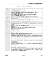
2211
22
FSW INTERLOCK TRIPPED
The Footswitch was closed for more then seven seconds.
2212
22
DRIVE LOCKED - JOYSTICK MOVED BEFORE FOOTSWITCH
A drive function was selected with Footswitch open.
2213
22
STEER LOCKED - SELECTED BEFORE FOOTSWITCH
A steer function was selected with Footswitch open.
2221
22
LIFT/SWING LOCKED - JOYSTICK MOVED BEFORE FOOT-
SWITCH
A lift / swing function was selected with Footswitch open.
2222
22
WAITING FOR FSW TO BE OPEN
The Footswitch was closed during Platform selection.
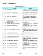
2245
22
FUNCTION PROBLEM - JIB SWING LEFT PERMANENTLY
SELECTED
Input was CLOSED during startup
2246
22
FUNCTION PROBLEM - JIB SWING RIGHT PERMANENTLY
SELECTED
Input was CLOSED during startup
2247
22
FUNCTION PROBLEM - PLATFORM ROTATE LEFT PERMA-
NENTLY SELECTED
Input was CLOSED during startup
2248
22
FUNCTION PROBLEM - PLATFORM ROTATE RIGHT PERMA-
NENTLY SELECTED
Input was CLOSED during startup
2249
22
FUNCTION PROBLEM - JIB LIFT UP PERMANENTLY SELECTED Input was CLOSED during startup
2250
22
FUNCTION PROBLEM - JIB LIFT DOWN PERMANENTLY
SELECTED
Input was CLOSED during startup
2251
22
FUNCTION PROBLEM - TELESCOPE IN PERMANENTLY
SELECTED
Input was CLOSED during startup
Содержание JLG E400AJP
Страница 2: ......
Страница 21: ...SECTION 1 SPECIFICATIONS 3121827 JLG Lift 1 7 Figure 1 2 Operator Maintenance Lubrication Diagram...
Страница 32: ...SECTION 1 SPECIFICATIONS 1 18 JLG Lift 3121827 NOTES...
Страница 42: ...SECTION 2 GENERAL 2 10 JLG Lift 3121827 NOTES...
Страница 54: ...SECTION 3 CHASSIS TURNTABLE 3 12 JLG Lift 3121827 Figure 3 3 Speed Sensor Orientation...
Страница 55: ...SECTION 3 CHASSIS TURNTABLE 3121827 JLG Lift 3 13 Figure 3 4 Frame Mounted Electrical Components Sheet 1 of 2...
Страница 56: ...SECTION 3 CHASSIS TURNTABLE 3 14 JLG Lift 3121827 Figure 3 5 Frame Mounted Electrical Components Sheet 2 of 2...
Страница 60: ...SECTION 3 CHASSIS TURNTABLE 3 18 JLG Lift 3121827 Figure 3 7 Steering Components and Spindles...
Страница 62: ...SECTION 3 CHASSIS TURNTABLE 3 20 JLG Lift 3121827 Figure 3 9 Tilt Sensor Location...
Страница 86: ...SECTION 3 CHASSIS TURNTABLE 3 44 JLG Lift 3121827 Figure 3 16 Swing Components...
Страница 88: ...SECTION 3 CHASSIS TURNTABLE 3 46 JLG Lift 3121827 Figure 3 18 Battery Cable Connections...
Страница 90: ...SECTION 3 CHASSIS TURNTABLE 3 48 JLG Lift 3121827 Figure 3 20 On Board Generator...
Страница 97: ...SECTION 3 CHASSIS TURNTABLE 3121827 JLG Lift 3 55 Figure 3 22 Generator Components...
Страница 100: ...SECTION 3 CHASSIS TURNTABLE 3 58 JLG Lift 3121827 Figure 3 23 Generator System Analyzer Flow Chart...
Страница 116: ...SECTION 3 CHASSIS TURNTABLE 3 74 JLG Lift 3121827 NOTES...
Страница 125: ...SECTION 4 BOOM PLATFORM 3121827 JLG Lift 4 9 Figure 4 8 Jib Platform Components and Attaching Hardware...
Страница 127: ...SECTION 4 BOOM PLATFORM 3121827 JLG Lift 4 11 Figure 4 10 Boom Limit Switches...
Страница 140: ...SECTION 4 BOOM PLATFORM 4 24 JLG Lift 3121827 Figure 4 13 Rotator Counterbalance Valve...
Страница 178: ...SECTION 5 HYDRAULICS 5 24 JLG Lift 3121827 Figure 5 26 HydraForce Cartridge Torque Value Chart...
Страница 179: ...SECTION 5 HYDRAULICS 3121827 JLG Lift 5 25 Figure 5 27 Main Valve Components Prior to S N 62642...
Страница 214: ...SECTION 6 JLG CONTROL SYSTEM 6 34 JLG Lift 3121827 NOTES...
Страница 257: ......

