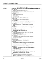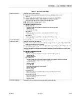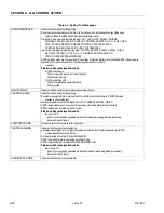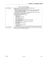
SECTION 6 - JLG CONTROL SYSTEM
3121827
– JLG Lift –
6-25
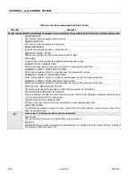
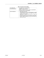
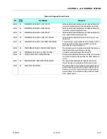
TESTING VALVES
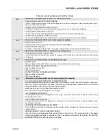
Indicates that the valve test is beginning.
Each valve is alternately energized and de-energized; checks are made for open-and short- circuit
valve coils.
The valves are tested in the order: PROP (main proportional), LL U, LL D, UL U, UL D, SWING L,
SWING R, SWING REST, LEVEL U, LEVEL D, ROTATE L, ROTATE R, JIB U, JIB D,
TELE I, TELE O, BYPASS, STEER L, STEER R, STEER PROP, BRAKE
NOTE: in platform mode, the foot switch must be closed.
NOTE: jib valves are not tested if JIB = NO
Problems which can be reported include:
CANT TEST VALVES
There is a wiring problem which prevents the valve test from functioning correctly.
Check valve wiring.
Check ground alarm wiring.
valve name S/C
The named valve is drawing too much current so is presumed to be short-circuit.
Check valve wiring.
valve name O/C
The named valve is drawing too little current so is presumed to be open-circuit.
Check valve wiring.
VALVE TEST DONE
Indicates that the valve test is complete (with or without faults).
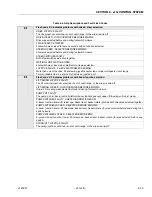
TESTING CONTS
Indicates that the contactor test is beginning.
In platform mode, the forward & reverse direction contactors are energized and de-energized; checks are made that they
close & open correctly and for short-circuit coils.
In platform and ground mode, the line contactor is energized and de-energized; checks are made that it closed & opened
correctly and for a short-circuit coil.
In platform mode, the positrac contactors are energized and de-energized; checks are made for short-circuit and open-
circuit coils.
Problems which can be reported include:
CANT TEST CONTS
There is a wiring problem which prevents the contactor test from functioning correctly.
Check power wiring.
Check contactor wiring.
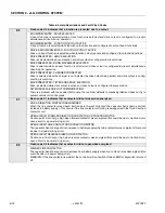
BAD CONT WIRING
There is a wiring problem which caused the capacitor bank to be charged when a direction contactor was
energized; probably the wiring to the contactor coils is incorrect.
Check contactor wiring.
Check power wiring.
cont name WELDED
The named contactor appears to have not opened.
Check named contactor.
Check power wiring.
cont name COIL S/C
The named contactor coil overloaded its driver circuit so is presumed to be short-circuit.
Check contactor wiring.
cont name DIDN’T CLOSE
The named contactor appears to have not closed.
Check contactor wiring.
Check power wiring.
CONT TEST DONE
Indicates that the contactor test is complete (with or without faults).
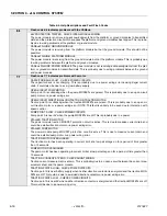
Table 6-7. System Test Messages
Содержание JLG E400AJP
Страница 2: ......
Страница 21: ...SECTION 1 SPECIFICATIONS 3121827 JLG Lift 1 7 Figure 1 2 Operator Maintenance Lubrication Diagram...
Страница 32: ...SECTION 1 SPECIFICATIONS 1 18 JLG Lift 3121827 NOTES...
Страница 42: ...SECTION 2 GENERAL 2 10 JLG Lift 3121827 NOTES...
Страница 54: ...SECTION 3 CHASSIS TURNTABLE 3 12 JLG Lift 3121827 Figure 3 3 Speed Sensor Orientation...
Страница 55: ...SECTION 3 CHASSIS TURNTABLE 3121827 JLG Lift 3 13 Figure 3 4 Frame Mounted Electrical Components Sheet 1 of 2...
Страница 56: ...SECTION 3 CHASSIS TURNTABLE 3 14 JLG Lift 3121827 Figure 3 5 Frame Mounted Electrical Components Sheet 2 of 2...
Страница 60: ...SECTION 3 CHASSIS TURNTABLE 3 18 JLG Lift 3121827 Figure 3 7 Steering Components and Spindles...
Страница 62: ...SECTION 3 CHASSIS TURNTABLE 3 20 JLG Lift 3121827 Figure 3 9 Tilt Sensor Location...
Страница 86: ...SECTION 3 CHASSIS TURNTABLE 3 44 JLG Lift 3121827 Figure 3 16 Swing Components...
Страница 88: ...SECTION 3 CHASSIS TURNTABLE 3 46 JLG Lift 3121827 Figure 3 18 Battery Cable Connections...
Страница 90: ...SECTION 3 CHASSIS TURNTABLE 3 48 JLG Lift 3121827 Figure 3 20 On Board Generator...
Страница 97: ...SECTION 3 CHASSIS TURNTABLE 3121827 JLG Lift 3 55 Figure 3 22 Generator Components...
Страница 100: ...SECTION 3 CHASSIS TURNTABLE 3 58 JLG Lift 3121827 Figure 3 23 Generator System Analyzer Flow Chart...
Страница 116: ...SECTION 3 CHASSIS TURNTABLE 3 74 JLG Lift 3121827 NOTES...
Страница 125: ...SECTION 4 BOOM PLATFORM 3121827 JLG Lift 4 9 Figure 4 8 Jib Platform Components and Attaching Hardware...
Страница 127: ...SECTION 4 BOOM PLATFORM 3121827 JLG Lift 4 11 Figure 4 10 Boom Limit Switches...
Страница 140: ...SECTION 4 BOOM PLATFORM 4 24 JLG Lift 3121827 Figure 4 13 Rotator Counterbalance Valve...
Страница 178: ...SECTION 5 HYDRAULICS 5 24 JLG Lift 3121827 Figure 5 26 HydraForce Cartridge Torque Value Chart...
Страница 179: ...SECTION 5 HYDRAULICS 3121827 JLG Lift 5 25 Figure 5 27 Main Valve Components Prior to S N 62642...
Страница 214: ...SECTION 6 JLG CONTROL SYSTEM 6 34 JLG Lift 3121827 NOTES...
Страница 257: ......

