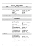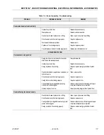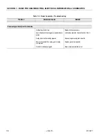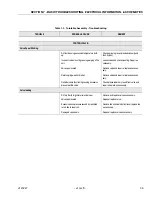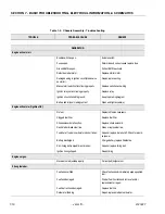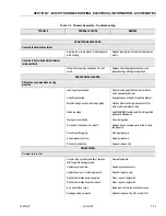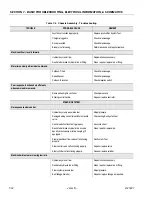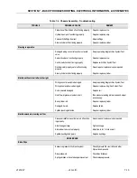
SECTION 6 - JLG CONTROL SYSTEM
3121827
– JLG Lift –
6-33
99133
99
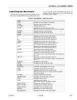
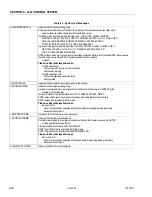
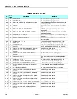
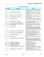
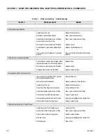
POWER MODULE FAILURE - HWFS CODE 15
Hardware failsafe tests failed because the hardware failsafe the
contactor drive failsafe did not trip within the allowed test time
99134
99
POWER MODULE FAILURE - HWFS CODE 16
Hardware failsafe tests failed because the hardware failsafe the
contactor drive failsafe tripped tooslowly
99135
99
POWER MODULE FAILURE - HWFS CODE 17
Hardware failsafe tests failed because the hardware failsafe the
drive contactor failsafe tripped too quickly
99136
99
POWER MODULE FAILURE - HWFS TEST STALLED
Hardware failsafe tests did not complete, but no reason can be
determined
99137
99
POWER MODULE FAILURE - LINE CONTACTOR DRIVER
The line contactor energized when the footswitch was CLOSED
before it was ON, this maybe due to a failed driver within the
power module, or a power wiring error
99138
99
POWER MODULE FAILURE - TEMPERATURE SENSOR
The temperature sensor measurement is invalid, this maybe due
to a disconnected wire within the power module.
99139
99
POWER MODULE FAILURE - CONTACTOR CODE 1
A contactor remained energized when turned OFF
99140
99
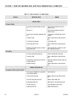
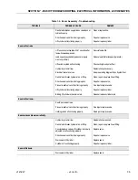
TILT MODULE FAILURE - INTERNAL ERROR
Startup test detected faulty tilt sensors, or voltages on the tilt sen-
sor are bad (could be caused if positilt is mounted upside down or
vertical
99141
99
GROUND MODULE - OBSOLETE ON THIS VEHICLE
The power module determined the hardware version of the
Ground module was incompatible with the current software
99142
99
48V PROTECTION TRIPPED
The power module is not receiving acknowledgements from the
platform module or ground module to transmitted data, and the
protection circuit which supplies the platform and ground mod-
ules has tripped. This maybe due to wiring problems at the plat-
form or groundmodule.
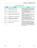
Table 6-8. Diagnostic Fault Codes
DTC
Flash
Code
Fault Message
Description
Содержание JLG E400AJP
Страница 2: ......
Страница 21: ...SECTION 1 SPECIFICATIONS 3121827 JLG Lift 1 7 Figure 1 2 Operator Maintenance Lubrication Diagram...
Страница 32: ...SECTION 1 SPECIFICATIONS 1 18 JLG Lift 3121827 NOTES...
Страница 42: ...SECTION 2 GENERAL 2 10 JLG Lift 3121827 NOTES...
Страница 54: ...SECTION 3 CHASSIS TURNTABLE 3 12 JLG Lift 3121827 Figure 3 3 Speed Sensor Orientation...
Страница 55: ...SECTION 3 CHASSIS TURNTABLE 3121827 JLG Lift 3 13 Figure 3 4 Frame Mounted Electrical Components Sheet 1 of 2...
Страница 56: ...SECTION 3 CHASSIS TURNTABLE 3 14 JLG Lift 3121827 Figure 3 5 Frame Mounted Electrical Components Sheet 2 of 2...
Страница 60: ...SECTION 3 CHASSIS TURNTABLE 3 18 JLG Lift 3121827 Figure 3 7 Steering Components and Spindles...
Страница 62: ...SECTION 3 CHASSIS TURNTABLE 3 20 JLG Lift 3121827 Figure 3 9 Tilt Sensor Location...
Страница 86: ...SECTION 3 CHASSIS TURNTABLE 3 44 JLG Lift 3121827 Figure 3 16 Swing Components...
Страница 88: ...SECTION 3 CHASSIS TURNTABLE 3 46 JLG Lift 3121827 Figure 3 18 Battery Cable Connections...
Страница 90: ...SECTION 3 CHASSIS TURNTABLE 3 48 JLG Lift 3121827 Figure 3 20 On Board Generator...
Страница 97: ...SECTION 3 CHASSIS TURNTABLE 3121827 JLG Lift 3 55 Figure 3 22 Generator Components...
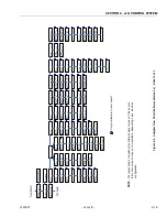
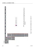
Страница 100: ...SECTION 3 CHASSIS TURNTABLE 3 58 JLG Lift 3121827 Figure 3 23 Generator System Analyzer Flow Chart...
Страница 116: ...SECTION 3 CHASSIS TURNTABLE 3 74 JLG Lift 3121827 NOTES...
Страница 125: ...SECTION 4 BOOM PLATFORM 3121827 JLG Lift 4 9 Figure 4 8 Jib Platform Components and Attaching Hardware...
Страница 127: ...SECTION 4 BOOM PLATFORM 3121827 JLG Lift 4 11 Figure 4 10 Boom Limit Switches...
Страница 140: ...SECTION 4 BOOM PLATFORM 4 24 JLG Lift 3121827 Figure 4 13 Rotator Counterbalance Valve...
Страница 178: ...SECTION 5 HYDRAULICS 5 24 JLG Lift 3121827 Figure 5 26 HydraForce Cartridge Torque Value Chart...
Страница 179: ...SECTION 5 HYDRAULICS 3121827 JLG Lift 5 25 Figure 5 27 Main Valve Components Prior to S N 62642...
Страница 214: ...SECTION 6 JLG CONTROL SYSTEM 6 34 JLG Lift 3121827 NOTES...
Страница 257: ......

