SECTION 7 - BASIC TROUBLESHOOTING, ELECTRICAL INFORMATION, & SCHEMATICS
3121827
– JLG Lift –
7-13
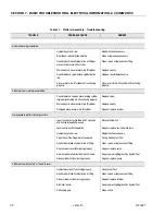
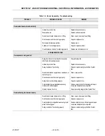
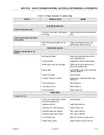
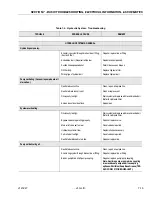
Proportional Flow Valve not functioning properly.
Repair or replace valve.
Hydraulic pump not functioning properly.
Repair or replace pump.
Personality Settings Incorrect.
Adjust settings.
Steer cylinder not functioning properly.
Repair or replace cylinder.
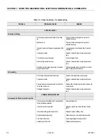
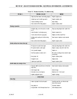
Steering inoperative.
Damaged wiring on control switch or solenoid
valve.
See proper wiring diagram/Run System Test.
Solenoid valve not functioning properly.
Repair or replace valve.
Control switch not functioning properly.
Replace switch/Run System Test.
Relief valve improperly set or not functioning
properly.
Reset, repair or replace valves as required.
Steer cylinder not functioning properly.
Repair or replace cylinder.
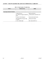
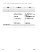
Machine will not steer left or to the right.
Wiring on control switch is damaged.
See proper wiring diagram/Run System Test.
Wiring on solenoid valve damaged.
Repair or replace wiring/Run System Test.
Coil in solenoid damaged.
Replace coil.
No oil flow or pressure to steer circuit.
Take pressure reading at steer valve and adjust
as necessary.
Bent cylinder rod.
Repair or replace cylinder.
Damaged tie rod.
Replace tie rod.
Cylinder packing defective.
Repair or replace cylinder.
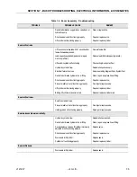
Machine wanders; steering not firm.
Crossover relief valve set too low or not function-
ing properly.
Reset, repair or replace valve as required.
Steer linkages loose.
Tighten linkage.
Steer wheel toe-in not set properly.
Adjust toe-in for 1/4 inch overall.
Spindle bushings badly worn.
Replace bushings.
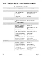
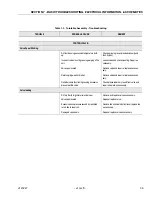
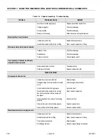
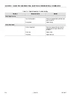
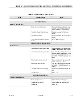
DRIVE BRAKE.
Brake Slips
Excessive pressure in hydraulic system.
Check hydraulic filter, restrictions in other
hydraulic components.
Disc plates worn.
Check disc thickness.
Springs broken or have taken a permanent set.
Check release pressure.
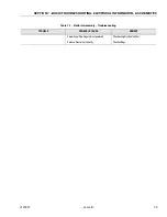
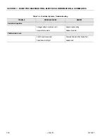
Table 7-4. Chassis Assembly - Troubleshooting
TROUBLE
PROBABLE CAUSE
REMEDY
Содержание JLG E400AJP
Страница 2: ......
Страница 21: ...SECTION 1 SPECIFICATIONS 3121827 JLG Lift 1 7 Figure 1 2 Operator Maintenance Lubrication Diagram...
Страница 32: ...SECTION 1 SPECIFICATIONS 1 18 JLG Lift 3121827 NOTES...
Страница 42: ...SECTION 2 GENERAL 2 10 JLG Lift 3121827 NOTES...
Страница 54: ...SECTION 3 CHASSIS TURNTABLE 3 12 JLG Lift 3121827 Figure 3 3 Speed Sensor Orientation...
Страница 55: ...SECTION 3 CHASSIS TURNTABLE 3121827 JLG Lift 3 13 Figure 3 4 Frame Mounted Electrical Components Sheet 1 of 2...
Страница 56: ...SECTION 3 CHASSIS TURNTABLE 3 14 JLG Lift 3121827 Figure 3 5 Frame Mounted Electrical Components Sheet 2 of 2...
Страница 60: ...SECTION 3 CHASSIS TURNTABLE 3 18 JLG Lift 3121827 Figure 3 7 Steering Components and Spindles...
Страница 62: ...SECTION 3 CHASSIS TURNTABLE 3 20 JLG Lift 3121827 Figure 3 9 Tilt Sensor Location...
Страница 86: ...SECTION 3 CHASSIS TURNTABLE 3 44 JLG Lift 3121827 Figure 3 16 Swing Components...
Страница 88: ...SECTION 3 CHASSIS TURNTABLE 3 46 JLG Lift 3121827 Figure 3 18 Battery Cable Connections...
Страница 90: ...SECTION 3 CHASSIS TURNTABLE 3 48 JLG Lift 3121827 Figure 3 20 On Board Generator...
Страница 97: ...SECTION 3 CHASSIS TURNTABLE 3121827 JLG Lift 3 55 Figure 3 22 Generator Components...
Страница 100: ...SECTION 3 CHASSIS TURNTABLE 3 58 JLG Lift 3121827 Figure 3 23 Generator System Analyzer Flow Chart...
Страница 116: ...SECTION 3 CHASSIS TURNTABLE 3 74 JLG Lift 3121827 NOTES...
Страница 125: ...SECTION 4 BOOM PLATFORM 3121827 JLG Lift 4 9 Figure 4 8 Jib Platform Components and Attaching Hardware...
Страница 127: ...SECTION 4 BOOM PLATFORM 3121827 JLG Lift 4 11 Figure 4 10 Boom Limit Switches...
Страница 140: ...SECTION 4 BOOM PLATFORM 4 24 JLG Lift 3121827 Figure 4 13 Rotator Counterbalance Valve...
Страница 178: ...SECTION 5 HYDRAULICS 5 24 JLG Lift 3121827 Figure 5 26 HydraForce Cartridge Torque Value Chart...
Страница 179: ...SECTION 5 HYDRAULICS 3121827 JLG Lift 5 25 Figure 5 27 Main Valve Components Prior to S N 62642...
Страница 214: ...SECTION 6 JLG CONTROL SYSTEM 6 34 JLG Lift 3121827 NOTES...
Страница 257: ......

