SECTION 4 - BOOM & PLATFORM
3121827
– JLG Lift –
4-25
Installation and Bleeding
After installation of the actuator on the equipment, it is
important that all safety devices such as tie rods or safety
cables are properly reattached.
To purge air from the hydraulic lines, connect them
together to create a closed loop and pump hydraulic fluid
through them. Review the hydraulic schematic to deter-
mine which hydraulic lines to connect. The linear feet and
inside diameter of the hydraulic supply lines together with
pump capacity will determine the amount of pumping time
required to fully purge the hydraulic system.
Bleeding may be necessary if excessive backlash is exhib-
ited after the actuator is connected to the hydraulic sys-
tem. The following steps are recommended when a
minimum of two gallons (8 liters) is purged.
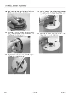
1.
Connect a 3/16" inside diameter x 5/16" outside
diameter x 5 foot clear, vinyl drain tube to each of the
two bleed nipples. Secure them with hose clamps.
Place the vinyl tubes in a clean 5-gallon container to
collect the purged oil. The oil can be returned to the
reservoir after this procedure is completed.
2.
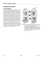
With an operator in the platform, open both bleed
nipples 1/4 turn. Hydraulically rotate the platform to
the end of rotation (either clockwise or counterclock-
wise), and maintain hydraulic pressure. Oil with
small air bubbles will be seen flowing through the
tubes. Allow a 1/2 gallon of fluid to be purged from
the actuator.
3.
Keep the fittings open and rotate the platform in the
opposite direction to the end position. Maintain
hydraulic pressure until an additional 1/4 gallon of
fluid is pumped into the container.
4.
Repeat steps 2 & 3. After the last 1/2 gallon is
purged, close both bleed nipples before rotating
away from the end position.
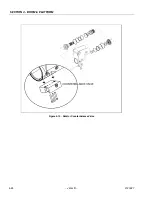
TYPICAL CONFIGURATION
OF ACTUATOR
Содержание JLG E400AJP
Страница 2: ......
Страница 21: ...SECTION 1 SPECIFICATIONS 3121827 JLG Lift 1 7 Figure 1 2 Operator Maintenance Lubrication Diagram...
Страница 32: ...SECTION 1 SPECIFICATIONS 1 18 JLG Lift 3121827 NOTES...
Страница 42: ...SECTION 2 GENERAL 2 10 JLG Lift 3121827 NOTES...
Страница 54: ...SECTION 3 CHASSIS TURNTABLE 3 12 JLG Lift 3121827 Figure 3 3 Speed Sensor Orientation...
Страница 55: ...SECTION 3 CHASSIS TURNTABLE 3121827 JLG Lift 3 13 Figure 3 4 Frame Mounted Electrical Components Sheet 1 of 2...
Страница 56: ...SECTION 3 CHASSIS TURNTABLE 3 14 JLG Lift 3121827 Figure 3 5 Frame Mounted Electrical Components Sheet 2 of 2...
Страница 60: ...SECTION 3 CHASSIS TURNTABLE 3 18 JLG Lift 3121827 Figure 3 7 Steering Components and Spindles...
Страница 62: ...SECTION 3 CHASSIS TURNTABLE 3 20 JLG Lift 3121827 Figure 3 9 Tilt Sensor Location...
Страница 86: ...SECTION 3 CHASSIS TURNTABLE 3 44 JLG Lift 3121827 Figure 3 16 Swing Components...
Страница 88: ...SECTION 3 CHASSIS TURNTABLE 3 46 JLG Lift 3121827 Figure 3 18 Battery Cable Connections...
Страница 90: ...SECTION 3 CHASSIS TURNTABLE 3 48 JLG Lift 3121827 Figure 3 20 On Board Generator...
Страница 97: ...SECTION 3 CHASSIS TURNTABLE 3121827 JLG Lift 3 55 Figure 3 22 Generator Components...
Страница 100: ...SECTION 3 CHASSIS TURNTABLE 3 58 JLG Lift 3121827 Figure 3 23 Generator System Analyzer Flow Chart...
Страница 116: ...SECTION 3 CHASSIS TURNTABLE 3 74 JLG Lift 3121827 NOTES...
Страница 125: ...SECTION 4 BOOM PLATFORM 3121827 JLG Lift 4 9 Figure 4 8 Jib Platform Components and Attaching Hardware...
Страница 127: ...SECTION 4 BOOM PLATFORM 3121827 JLG Lift 4 11 Figure 4 10 Boom Limit Switches...
Страница 140: ...SECTION 4 BOOM PLATFORM 4 24 JLG Lift 3121827 Figure 4 13 Rotator Counterbalance Valve...
Страница 178: ...SECTION 5 HYDRAULICS 5 24 JLG Lift 3121827 Figure 5 26 HydraForce Cartridge Torque Value Chart...
Страница 179: ...SECTION 5 HYDRAULICS 3121827 JLG Lift 5 25 Figure 5 27 Main Valve Components Prior to S N 62642...
Страница 214: ...SECTION 6 JLG CONTROL SYSTEM 6 34 JLG Lift 3121827 NOTES...
Страница 257: ......


