SECTION 2 - GENERAL
3121827
– JLG Lift –
2-7
Functions/Controls
9
Platform Controls
5
5
6
6
Ground Controls
5
5
6
6
Function Control Locks, Guards, or Detents
1,5
1,5
5
5
Footswitch
1,5
5
5
Emergency Stop Switches (Ground & Platform)
5
5
5
Function Limit or Cutout Switch Systems
5
5
Capacity Indicator
5
Drive Brakes
5
Swing Brakes
5
Boom Synchronization/Sequencing Systems
5
Manual Descent or Auxiliary Power
5
5
Power System
9
Engine Idle, Throttle, and RPM
N/A
Engine Fluids (Oil, Coolant, Fuel)
N/A
Air/Fuel Filter
1,7
7
7
Exhaust System
1,9
9
9
Batteries
5
1,9
19
Battery Fluid
11
11
11
Battery Charger
5
5
Fuel Reservoir, Cap, and Breather
N/A
Hydraulic/Electric System
9
Hydraulic Pumps
1,9
1,2,9
Hydraulic Cylinders
1,9,7
2
1,2,9
1,2,9
Cylinder Attachment Pins and Pin Retainers
1,9
1,2
1,2
Hydraulic Hoses, Lines, and Fittings
1,9
12
1,2,9,12
1,2,9,12
Hydraulic Reservoir, Cap, and Breather
11
1,9
2
1,5
1,5
24
Hydraulic Filter
1,9
7
7
Hydraulic Fluid
11
7,11
7,11
Electrical Connections
1
20
20
Instruments, Gauges, Switches, Lights, Horn
1
5,23
General
Operators and Safety Manuals in Storage Box
21
21
21
ANSI and EMI Manuals/Handbooks Installed
21
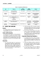
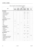
Table 2-3. Inspection and Preventive Maintenance Schedule
AREA
INTERVAL
Pre-Start
1
Inspection
Weekly
Preventive
Maintenance
Monthly
Preventive
Maintenance
Pre-Delivery
2
or Frequent
3
Inspection
Annual
4
(Yearly)
Inspection
Every 2
Years
Содержание JLG E400AJP
Страница 2: ......
Страница 21: ...SECTION 1 SPECIFICATIONS 3121827 JLG Lift 1 7 Figure 1 2 Operator Maintenance Lubrication Diagram...
Страница 32: ...SECTION 1 SPECIFICATIONS 1 18 JLG Lift 3121827 NOTES...
Страница 42: ...SECTION 2 GENERAL 2 10 JLG Lift 3121827 NOTES...
Страница 54: ...SECTION 3 CHASSIS TURNTABLE 3 12 JLG Lift 3121827 Figure 3 3 Speed Sensor Orientation...
Страница 55: ...SECTION 3 CHASSIS TURNTABLE 3121827 JLG Lift 3 13 Figure 3 4 Frame Mounted Electrical Components Sheet 1 of 2...
Страница 56: ...SECTION 3 CHASSIS TURNTABLE 3 14 JLG Lift 3121827 Figure 3 5 Frame Mounted Electrical Components Sheet 2 of 2...
Страница 60: ...SECTION 3 CHASSIS TURNTABLE 3 18 JLG Lift 3121827 Figure 3 7 Steering Components and Spindles...
Страница 62: ...SECTION 3 CHASSIS TURNTABLE 3 20 JLG Lift 3121827 Figure 3 9 Tilt Sensor Location...
Страница 86: ...SECTION 3 CHASSIS TURNTABLE 3 44 JLG Lift 3121827 Figure 3 16 Swing Components...
Страница 88: ...SECTION 3 CHASSIS TURNTABLE 3 46 JLG Lift 3121827 Figure 3 18 Battery Cable Connections...
Страница 90: ...SECTION 3 CHASSIS TURNTABLE 3 48 JLG Lift 3121827 Figure 3 20 On Board Generator...
Страница 97: ...SECTION 3 CHASSIS TURNTABLE 3121827 JLG Lift 3 55 Figure 3 22 Generator Components...
Страница 100: ...SECTION 3 CHASSIS TURNTABLE 3 58 JLG Lift 3121827 Figure 3 23 Generator System Analyzer Flow Chart...
Страница 116: ...SECTION 3 CHASSIS TURNTABLE 3 74 JLG Lift 3121827 NOTES...
Страница 125: ...SECTION 4 BOOM PLATFORM 3121827 JLG Lift 4 9 Figure 4 8 Jib Platform Components and Attaching Hardware...
Страница 127: ...SECTION 4 BOOM PLATFORM 3121827 JLG Lift 4 11 Figure 4 10 Boom Limit Switches...
Страница 140: ...SECTION 4 BOOM PLATFORM 4 24 JLG Lift 3121827 Figure 4 13 Rotator Counterbalance Valve...
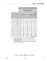
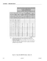
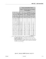
Страница 178: ...SECTION 5 HYDRAULICS 5 24 JLG Lift 3121827 Figure 5 26 HydraForce Cartridge Torque Value Chart...
Страница 179: ...SECTION 5 HYDRAULICS 3121827 JLG Lift 5 25 Figure 5 27 Main Valve Components Prior to S N 62642...
Страница 214: ...SECTION 6 JLG CONTROL SYSTEM 6 34 JLG Lift 3121827 NOTES...
Страница 257: ......

