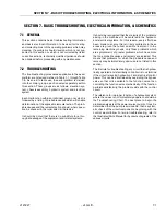
SECTION 7 - BASIC TROUBLESHOOTING, ELECTRICAL INFORMATION, & SCHEMATICS
7-6
– JLG Lift –
3121827
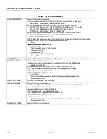
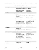
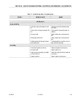
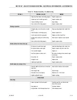
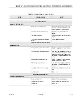
Function Speed and Drive Speed does not operate below horizontal.
Damaged wiring on level limit switch.
Repair or replace wiring/Run System Test
Creep Switch Open.
Replace switch/Run System Test
Machine Tilted
Level machine.
Speed Sensor Failure.
Replace Sensor.
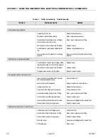
LOWER LIFT FUNCTION.
If the boom assembly does not fully lower.
The Mid and Lower Booms are out of synchroni-
zation.
Refer to synchronize procedure.
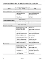
MAIN TELESCOPE SYSTEM.
No response to telescope control.
Telescope function not activated within 7 sec-
onds after footswitch was depressed.
Recycle footswitch.
Telescope control switch inoperative.
Repair or replace control switch/Run System
Test
Hydraulic system oil low.
Replenish oil as necessary.
Damaged wiring on control switch or solenoid
valve.
Repair or replace wiring/Run System Test
Directional valve not functioning properly.
Repair or replace valve.
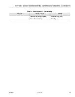
Restricted or broken supply line on valve bank or
hydraulic pump.
Clean or replace line.
Proportional Flow Regulator Not Powered.
Check wiring/Run System Test.
Telescope cylinder not functioning properly.
Repair or replace cylinder.
Hydraulic pump not functioning properly.
Repair or replace pump/Run System Test.
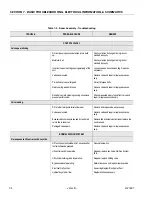
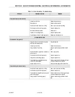
Boom will not extend.
Telescope function not activated within 7 sec-
onds after footswitch was depressed.
Recycle footswitch.
Directional valve not functioning properly.
Repair or replace control valve.
Restricted or broken hydraulic line or fitting.
Clean, repair, or replace line or fitting.
Pressure setting incorrect.
Check pressure/re-adjust as necessary.
Telescope cylinder not functioning properly.
Repair or replace cylinder.
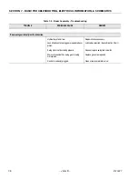
Personality Setting incorrect.
Set to Factory Default.
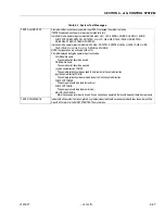
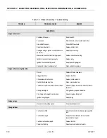
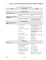
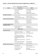
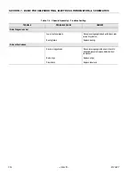
Table 7-2. Boom Assembly - Troubleshooting
TROUBLE
PROBABLE CAUSE
REMEDY
Содержание JLG E400AJP
Страница 2: ......
Страница 21: ...SECTION 1 SPECIFICATIONS 3121827 JLG Lift 1 7 Figure 1 2 Operator Maintenance Lubrication Diagram...
Страница 32: ...SECTION 1 SPECIFICATIONS 1 18 JLG Lift 3121827 NOTES...
Страница 42: ...SECTION 2 GENERAL 2 10 JLG Lift 3121827 NOTES...
Страница 54: ...SECTION 3 CHASSIS TURNTABLE 3 12 JLG Lift 3121827 Figure 3 3 Speed Sensor Orientation...
Страница 55: ...SECTION 3 CHASSIS TURNTABLE 3121827 JLG Lift 3 13 Figure 3 4 Frame Mounted Electrical Components Sheet 1 of 2...
Страница 56: ...SECTION 3 CHASSIS TURNTABLE 3 14 JLG Lift 3121827 Figure 3 5 Frame Mounted Electrical Components Sheet 2 of 2...
Страница 60: ...SECTION 3 CHASSIS TURNTABLE 3 18 JLG Lift 3121827 Figure 3 7 Steering Components and Spindles...
Страница 62: ...SECTION 3 CHASSIS TURNTABLE 3 20 JLG Lift 3121827 Figure 3 9 Tilt Sensor Location...
Страница 86: ...SECTION 3 CHASSIS TURNTABLE 3 44 JLG Lift 3121827 Figure 3 16 Swing Components...
Страница 88: ...SECTION 3 CHASSIS TURNTABLE 3 46 JLG Lift 3121827 Figure 3 18 Battery Cable Connections...
Страница 90: ...SECTION 3 CHASSIS TURNTABLE 3 48 JLG Lift 3121827 Figure 3 20 On Board Generator...
Страница 97: ...SECTION 3 CHASSIS TURNTABLE 3121827 JLG Lift 3 55 Figure 3 22 Generator Components...
Страница 100: ...SECTION 3 CHASSIS TURNTABLE 3 58 JLG Lift 3121827 Figure 3 23 Generator System Analyzer Flow Chart...
Страница 116: ...SECTION 3 CHASSIS TURNTABLE 3 74 JLG Lift 3121827 NOTES...
Страница 125: ...SECTION 4 BOOM PLATFORM 3121827 JLG Lift 4 9 Figure 4 8 Jib Platform Components and Attaching Hardware...
Страница 127: ...SECTION 4 BOOM PLATFORM 3121827 JLG Lift 4 11 Figure 4 10 Boom Limit Switches...
Страница 140: ...SECTION 4 BOOM PLATFORM 4 24 JLG Lift 3121827 Figure 4 13 Rotator Counterbalance Valve...
Страница 178: ...SECTION 5 HYDRAULICS 5 24 JLG Lift 3121827 Figure 5 26 HydraForce Cartridge Torque Value Chart...
Страница 179: ...SECTION 5 HYDRAULICS 3121827 JLG Lift 5 25 Figure 5 27 Main Valve Components Prior to S N 62642...
Страница 214: ...SECTION 6 JLG CONTROL SYSTEM 6 34 JLG Lift 3121827 NOTES...
Страница 257: ......

