SECTION 5 - HYDRAULICS
3121827
– JLG Lift –
5-1
SECTION 5. HYDRAULICS
5.1 LUBRICATING O-RINGS IN THE
HYDRAULIC SYSTEM
When assembling connectors in the hydraulic that use o-
ring fittings, it is necessary to lubricate all fittings with
hydraulic oil prior to assembly. To lubricate the fittings, use
one of the following procedures.
NOTE:
All O-ring fittings must be pre-lubricated with hydrau-
lic oil prior to assembly.
Cup and Brush
The following is needed to correctly oil the o-ring in this
manner:
• A small container for hydraulic oil
• Small paint brush
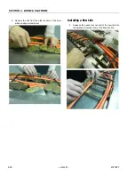
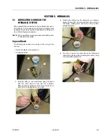
1.
Hold the fitting in one hand while using the brush
with the other hand to dip into the container.
Remove excess hydraulic oil from the brush so an
even film of oil is applied on the o-ring.
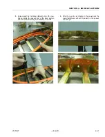
2.
Holding the fitting over the hydraulic oil container,
brush an even film of oil around the entire o-ring in
the fitting, making sure the entire o-ring is com-
pletely saturated.
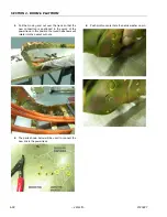
3.
Turn the o-ring on the other side of the fitting and
repeat the previous step, ensuring the entire o-ring
is coated with hydraulic oil.
Содержание JLG E400AJP
Страница 2: ......
Страница 21: ...SECTION 1 SPECIFICATIONS 3121827 JLG Lift 1 7 Figure 1 2 Operator Maintenance Lubrication Diagram...
Страница 32: ...SECTION 1 SPECIFICATIONS 1 18 JLG Lift 3121827 NOTES...
Страница 42: ...SECTION 2 GENERAL 2 10 JLG Lift 3121827 NOTES...
Страница 54: ...SECTION 3 CHASSIS TURNTABLE 3 12 JLG Lift 3121827 Figure 3 3 Speed Sensor Orientation...
Страница 55: ...SECTION 3 CHASSIS TURNTABLE 3121827 JLG Lift 3 13 Figure 3 4 Frame Mounted Electrical Components Sheet 1 of 2...
Страница 56: ...SECTION 3 CHASSIS TURNTABLE 3 14 JLG Lift 3121827 Figure 3 5 Frame Mounted Electrical Components Sheet 2 of 2...
Страница 60: ...SECTION 3 CHASSIS TURNTABLE 3 18 JLG Lift 3121827 Figure 3 7 Steering Components and Spindles...
Страница 62: ...SECTION 3 CHASSIS TURNTABLE 3 20 JLG Lift 3121827 Figure 3 9 Tilt Sensor Location...
Страница 86: ...SECTION 3 CHASSIS TURNTABLE 3 44 JLG Lift 3121827 Figure 3 16 Swing Components...
Страница 88: ...SECTION 3 CHASSIS TURNTABLE 3 46 JLG Lift 3121827 Figure 3 18 Battery Cable Connections...
Страница 90: ...SECTION 3 CHASSIS TURNTABLE 3 48 JLG Lift 3121827 Figure 3 20 On Board Generator...
Страница 97: ...SECTION 3 CHASSIS TURNTABLE 3121827 JLG Lift 3 55 Figure 3 22 Generator Components...
Страница 100: ...SECTION 3 CHASSIS TURNTABLE 3 58 JLG Lift 3121827 Figure 3 23 Generator System Analyzer Flow Chart...
Страница 116: ...SECTION 3 CHASSIS TURNTABLE 3 74 JLG Lift 3121827 NOTES...
Страница 125: ...SECTION 4 BOOM PLATFORM 3121827 JLG Lift 4 9 Figure 4 8 Jib Platform Components and Attaching Hardware...
Страница 127: ...SECTION 4 BOOM PLATFORM 3121827 JLG Lift 4 11 Figure 4 10 Boom Limit Switches...
Страница 140: ...SECTION 4 BOOM PLATFORM 4 24 JLG Lift 3121827 Figure 4 13 Rotator Counterbalance Valve...
Страница 178: ...SECTION 5 HYDRAULICS 5 24 JLG Lift 3121827 Figure 5 26 HydraForce Cartridge Torque Value Chart...
Страница 179: ...SECTION 5 HYDRAULICS 3121827 JLG Lift 5 25 Figure 5 27 Main Valve Components Prior to S N 62642...
Страница 214: ...SECTION 6 JLG CONTROL SYSTEM 6 34 JLG Lift 3121827 NOTES...
Страница 257: ......


