SECTION 3 - CHASSIS & TURNTABLE
3-24
– JLG Lift –
3121827
Preparation Before Disassembly
• Before you disassemble the motor unit or any of its
components read this entire section. It provides impor-
tant information on parts and procedures you will need
to know to service the motor.
• Thoroughly clean off all outside dirt, especially from
around fittings and hose connections, before discon-
necting and removing the motor. Remove rust or corro-
sion from coupling shaft.
• Remove coupling shaft connections and hose fittings
and immediately plug port holes and fluid lines.
• Remove the motor from system, drain it of fluid and
take it to a clean work surface.
• Clean and dry the motor before you start to disassem-
ble the unit.
• As you disassemble the motor clean all parts, except
seals, in clean petroleum-based solvent, and blow
them dry.
PETROLEUM-BASE SOLVENTS ARE FLAMMABLE. BE EXTREMELY
CAREFUL WHEN USING ANY SOLVENT. EVEN A SMALL EXPLO-
SION OR FIRE COULD CAUSE INJURY OR DEATH.
WEAR EYE PROTECTION AND BE SURE TO COMPLY WITH OSHA
OR OTHER MAXIMUM AIR PRESSURE REQUIREMENTS.
NEVER STEAM OR HIGH PRESSURE WASH HYDRAULIC COMPO-
NENTS. DO NOT FORCE OR ABUSE CLOSELY FITTED PARTS.
• Keep parts separate to avoid nicks and burrs.
• Discard all seals and seal rings as they are removed
from the motor. Replace all seals, seal rings and any
damaged or worn parts with OEM approved service
parts.
Disassembly and Inspection
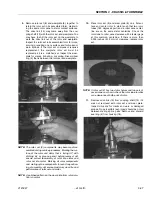
1.
Place the motor in a soft jawed vice, with coupling
shaft (12) pointed down and the vise jaws clamping
firmly on the sides of the housing (18) mounting
flange or port bosses. Remove manifold port O-
Rings if applicable.
IF THE MOTOR IS NOT FIRMLY HELD IN THE VISE, IT COULD BE
DISLODGED DURING THE SERVICE PROCEDURES, CAUSING
INJURY.
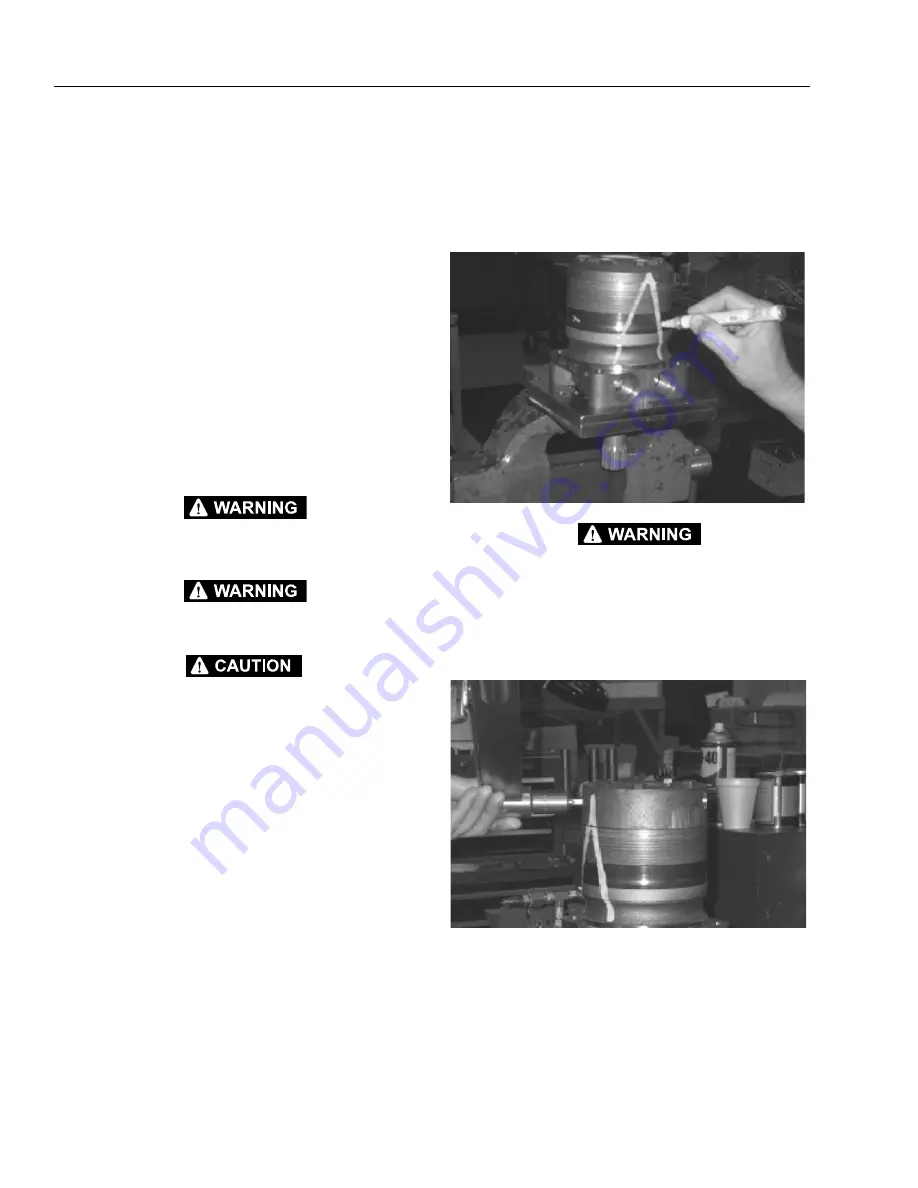
2.
Scribe an alignment mark down and across the
motor components from end cover (2) to housing
(18) to facilitate reassembly orientation where
required.
Содержание JLG E400AJP
Страница 2: ......
Страница 21: ...SECTION 1 SPECIFICATIONS 3121827 JLG Lift 1 7 Figure 1 2 Operator Maintenance Lubrication Diagram...
Страница 32: ...SECTION 1 SPECIFICATIONS 1 18 JLG Lift 3121827 NOTES...
Страница 42: ...SECTION 2 GENERAL 2 10 JLG Lift 3121827 NOTES...
Страница 54: ...SECTION 3 CHASSIS TURNTABLE 3 12 JLG Lift 3121827 Figure 3 3 Speed Sensor Orientation...
Страница 55: ...SECTION 3 CHASSIS TURNTABLE 3121827 JLG Lift 3 13 Figure 3 4 Frame Mounted Electrical Components Sheet 1 of 2...
Страница 56: ...SECTION 3 CHASSIS TURNTABLE 3 14 JLG Lift 3121827 Figure 3 5 Frame Mounted Electrical Components Sheet 2 of 2...
Страница 60: ...SECTION 3 CHASSIS TURNTABLE 3 18 JLG Lift 3121827 Figure 3 7 Steering Components and Spindles...
Страница 62: ...SECTION 3 CHASSIS TURNTABLE 3 20 JLG Lift 3121827 Figure 3 9 Tilt Sensor Location...
Страница 86: ...SECTION 3 CHASSIS TURNTABLE 3 44 JLG Lift 3121827 Figure 3 16 Swing Components...
Страница 88: ...SECTION 3 CHASSIS TURNTABLE 3 46 JLG Lift 3121827 Figure 3 18 Battery Cable Connections...
Страница 90: ...SECTION 3 CHASSIS TURNTABLE 3 48 JLG Lift 3121827 Figure 3 20 On Board Generator...
Страница 97: ...SECTION 3 CHASSIS TURNTABLE 3121827 JLG Lift 3 55 Figure 3 22 Generator Components...
Страница 100: ...SECTION 3 CHASSIS TURNTABLE 3 58 JLG Lift 3121827 Figure 3 23 Generator System Analyzer Flow Chart...
Страница 116: ...SECTION 3 CHASSIS TURNTABLE 3 74 JLG Lift 3121827 NOTES...
Страница 125: ...SECTION 4 BOOM PLATFORM 3121827 JLG Lift 4 9 Figure 4 8 Jib Platform Components and Attaching Hardware...
Страница 127: ...SECTION 4 BOOM PLATFORM 3121827 JLG Lift 4 11 Figure 4 10 Boom Limit Switches...
Страница 140: ...SECTION 4 BOOM PLATFORM 4 24 JLG Lift 3121827 Figure 4 13 Rotator Counterbalance Valve...
Страница 178: ...SECTION 5 HYDRAULICS 5 24 JLG Lift 3121827 Figure 5 26 HydraForce Cartridge Torque Value Chart...
Страница 179: ...SECTION 5 HYDRAULICS 3121827 JLG Lift 5 25 Figure 5 27 Main Valve Components Prior to S N 62642...
Страница 214: ...SECTION 6 JLG CONTROL SYSTEM 6 34 JLG Lift 3121827 NOTES...
Страница 257: ......


