SECTION 7 - BASIC TROUBLESHOOTING, ELECTRICAL INFORMATION, & SCHEMATICS
3121827
– JLG Lift –
7-17
.
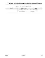
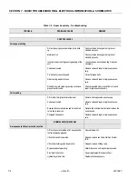
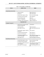
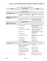
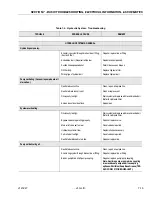
Table 7-6. Electrical System - Troubleshooting
TROUBLE
PROBABLE CAUSE
REMEDY
PLATFORM CONTROLS.
No power to platform controls.
15 Amp self-reset circuit breaker open.
Check footswitch to ensure that both switches
are making contact when pedal is depressed.
Repair or replace footswitch as necessary.
Contact block in footswitch malfunctioning.
Repair, replace or adjust contact block as
required.
Faulty power circuit wiring.
Check wiring continuity. Refer to proper wiring
diagram.
Platform EMS or Ground EMS switch in wrong
position.
Place switch to correct position.
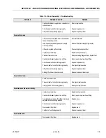
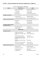
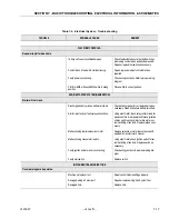
ENGINE STARTER SYSTEM (GENERATOR).
Starter will not crank.
Discharged battery or loose battery terminals.
Check and charge battery or replace battery as
necessary. Clean and secure battery terminals.
Starter relay faulty or faulty relay connections.
Using a test meter, check relay coil terminals for
presence of electrical power and for energization
of relay coil. Also check relay terminals for cor-
rect switching of contacts. Replace relay as nec-
essary.
Malfunctioning starter solenoid or motor.
Replace solenoid or motor in accordance with
applicable manufacturer’s manual.
Malfunctioning manual start switch.
Using a test meter, check ignition switch for cor-
rect switching of contacts. Replace switch as
necessary.
Faulty ignition and/or starter circuit wiring.
Check wiring continuity. See proper wiring dia-
gram.
Faulty start switch.
Replace switch.
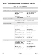
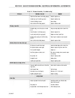
INSTRUMENTS AND INDICATORS.
Travel warning horn inoperative.
Machine set-up incorrect.
Adjust control module settings properly.
Damaged wiring in horn circuit.
Repair or replace wiring/Run System Test.
Damaged horn.
Replace horn.
Содержание JLG E400AJP
Страница 2: ......
Страница 21: ...SECTION 1 SPECIFICATIONS 3121827 JLG Lift 1 7 Figure 1 2 Operator Maintenance Lubrication Diagram...
Страница 32: ...SECTION 1 SPECIFICATIONS 1 18 JLG Lift 3121827 NOTES...
Страница 42: ...SECTION 2 GENERAL 2 10 JLG Lift 3121827 NOTES...
Страница 54: ...SECTION 3 CHASSIS TURNTABLE 3 12 JLG Lift 3121827 Figure 3 3 Speed Sensor Orientation...
Страница 55: ...SECTION 3 CHASSIS TURNTABLE 3121827 JLG Lift 3 13 Figure 3 4 Frame Mounted Electrical Components Sheet 1 of 2...
Страница 56: ...SECTION 3 CHASSIS TURNTABLE 3 14 JLG Lift 3121827 Figure 3 5 Frame Mounted Electrical Components Sheet 2 of 2...
Страница 60: ...SECTION 3 CHASSIS TURNTABLE 3 18 JLG Lift 3121827 Figure 3 7 Steering Components and Spindles...
Страница 62: ...SECTION 3 CHASSIS TURNTABLE 3 20 JLG Lift 3121827 Figure 3 9 Tilt Sensor Location...
Страница 86: ...SECTION 3 CHASSIS TURNTABLE 3 44 JLG Lift 3121827 Figure 3 16 Swing Components...
Страница 88: ...SECTION 3 CHASSIS TURNTABLE 3 46 JLG Lift 3121827 Figure 3 18 Battery Cable Connections...
Страница 90: ...SECTION 3 CHASSIS TURNTABLE 3 48 JLG Lift 3121827 Figure 3 20 On Board Generator...
Страница 97: ...SECTION 3 CHASSIS TURNTABLE 3121827 JLG Lift 3 55 Figure 3 22 Generator Components...
Страница 100: ...SECTION 3 CHASSIS TURNTABLE 3 58 JLG Lift 3121827 Figure 3 23 Generator System Analyzer Flow Chart...
Страница 116: ...SECTION 3 CHASSIS TURNTABLE 3 74 JLG Lift 3121827 NOTES...
Страница 125: ...SECTION 4 BOOM PLATFORM 3121827 JLG Lift 4 9 Figure 4 8 Jib Platform Components and Attaching Hardware...
Страница 127: ...SECTION 4 BOOM PLATFORM 3121827 JLG Lift 4 11 Figure 4 10 Boom Limit Switches...
Страница 140: ...SECTION 4 BOOM PLATFORM 4 24 JLG Lift 3121827 Figure 4 13 Rotator Counterbalance Valve...
Страница 178: ...SECTION 5 HYDRAULICS 5 24 JLG Lift 3121827 Figure 5 26 HydraForce Cartridge Torque Value Chart...
Страница 179: ...SECTION 5 HYDRAULICS 3121827 JLG Lift 5 25 Figure 5 27 Main Valve Components Prior to S N 62642...
Страница 214: ...SECTION 6 JLG CONTROL SYSTEM 6 34 JLG Lift 3121827 NOTES...
Страница 257: ......

