SECTION 5 - HYDRAULICS
3121827
– JLG Lift –
5-19
19.
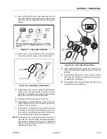
Continue pushing the rod into the barrel until the cyl-
inder head gland can be inserted into the barrel cyl-
inder.
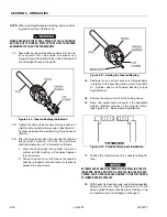
20.
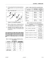
Secure the cylinder head gland using the washer
ring and socket head bolts.
21.
After the cylinder has been reassembled, the rod
should be pushed all the way in (fully retracted) prior
to the reinstallation of any holding valve or valves.
22.
If applicable, install the cartridge-type holding valve
and fittings in the rod port block, using new o-rings
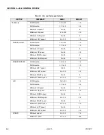
as applicable. (See Table 5-3, Holding Valve Torque
Specifications).
IF THE CYLINDER IS TO BE TESTED PRIOR TO INSTALLATION ON
THE MACHINE, EXTREME CARE SHOULD BE USED TO INSURE
THAT THE OUTER END OF THE ROD IS SUPPORTED. USE EITHER
A TRAVELING OVERHEAD HOIST, FORK-LIFT, OR OTHER MEANS
TO SUPPORT THE OVERHANGING WEIGHT OF THE EXTENDING
ROD.
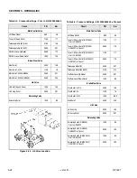
Table 5-1.Cylinder Head and Tapered Bushing Torque
Specifications
Description
Head Torque Value
(Wet)
Tapered Bushing
Torque Value (Wet)
Jib. Cylinder
41 Nm
(30 ft. lbs.)
7 Nm
(5 ft. lbs.)
Level Cylinder
41 Nm
(30 ft. lbs.)
7 Nm
(5 ft. lbs.)
Master Cylinder
41 Nm
(30 ft. lbs.)
7 Nm
(5 ft. lbs.)
Master Cylinder
E/M400A,E/M450A,
108 Nm
(80 ft. lbs.)
N/A
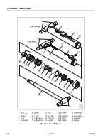
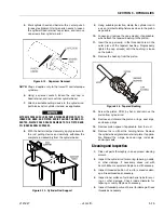
Figure 5-23. Rod Assembly Installation
Table 5-2. Cylinder Piston Nut Torque Specifications)
Description
Nut Torque
Valve (Wet)
Setscrew
Torque Value
(Dry)
Upper
Lift Cylinder
200 ft. lbs.
(270Nm)
100 in. lbs.
(11 Nm)
Mid
Lift Cylinder
400 ft. lbs.
(542 Nm)
100 in. lbs.
(11 Nm)
Mid
Lift Cylinder
E400An
200 ft.lbs.
(270 Nm)
100 in. lbs
11 (Nm)
Lower
Lift Cylinder
400 ft. lbs.
(542 Nm)
100 in. lbs.
(11 Nm)
Table 5-3. Holding Valve Torque Specifications
Description
Torque Value
SUN - 7/8 HEX M20 X 1.5 THDS.
30-35 ft. lbs.
(41-48 Nm)
SUN - 1 1/8 HEX 1 -14 UNS THDS.
45-50 ft. lbs.
(61-68 Nm)
SUN - 1 1/4 HEX M36 X 2 THDS.
150-160 ft. lbs.
(204-217 Nm)
RACINE - 1 1/8 HEX 1 1/16 - 12 THDS.
50-55 ft. lbs.
(68-75 Nm)
RACINE - 1 3/8 HEX 1 3/16 - 12 THDS.
75-80 ft. lbs.
(102-109 Nm)
RACINE - 1 7/8 HEX 1 5/8 - 12 THDS.
100-110 ft. lbs.
(136-149 Nm)
Содержание JLG E400AJP
Страница 2: ......
Страница 21: ...SECTION 1 SPECIFICATIONS 3121827 JLG Lift 1 7 Figure 1 2 Operator Maintenance Lubrication Diagram...
Страница 32: ...SECTION 1 SPECIFICATIONS 1 18 JLG Lift 3121827 NOTES...
Страница 42: ...SECTION 2 GENERAL 2 10 JLG Lift 3121827 NOTES...
Страница 54: ...SECTION 3 CHASSIS TURNTABLE 3 12 JLG Lift 3121827 Figure 3 3 Speed Sensor Orientation...
Страница 55: ...SECTION 3 CHASSIS TURNTABLE 3121827 JLG Lift 3 13 Figure 3 4 Frame Mounted Electrical Components Sheet 1 of 2...
Страница 56: ...SECTION 3 CHASSIS TURNTABLE 3 14 JLG Lift 3121827 Figure 3 5 Frame Mounted Electrical Components Sheet 2 of 2...
Страница 60: ...SECTION 3 CHASSIS TURNTABLE 3 18 JLG Lift 3121827 Figure 3 7 Steering Components and Spindles...
Страница 62: ...SECTION 3 CHASSIS TURNTABLE 3 20 JLG Lift 3121827 Figure 3 9 Tilt Sensor Location...
Страница 86: ...SECTION 3 CHASSIS TURNTABLE 3 44 JLG Lift 3121827 Figure 3 16 Swing Components...
Страница 88: ...SECTION 3 CHASSIS TURNTABLE 3 46 JLG Lift 3121827 Figure 3 18 Battery Cable Connections...
Страница 90: ...SECTION 3 CHASSIS TURNTABLE 3 48 JLG Lift 3121827 Figure 3 20 On Board Generator...
Страница 97: ...SECTION 3 CHASSIS TURNTABLE 3121827 JLG Lift 3 55 Figure 3 22 Generator Components...
Страница 100: ...SECTION 3 CHASSIS TURNTABLE 3 58 JLG Lift 3121827 Figure 3 23 Generator System Analyzer Flow Chart...
Страница 116: ...SECTION 3 CHASSIS TURNTABLE 3 74 JLG Lift 3121827 NOTES...
Страница 125: ...SECTION 4 BOOM PLATFORM 3121827 JLG Lift 4 9 Figure 4 8 Jib Platform Components and Attaching Hardware...
Страница 127: ...SECTION 4 BOOM PLATFORM 3121827 JLG Lift 4 11 Figure 4 10 Boom Limit Switches...
Страница 140: ...SECTION 4 BOOM PLATFORM 4 24 JLG Lift 3121827 Figure 4 13 Rotator Counterbalance Valve...
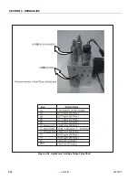
Страница 178: ...SECTION 5 HYDRAULICS 5 24 JLG Lift 3121827 Figure 5 26 HydraForce Cartridge Torque Value Chart...
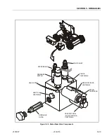
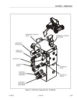
Страница 179: ...SECTION 5 HYDRAULICS 3121827 JLG Lift 5 25 Figure 5 27 Main Valve Components Prior to S N 62642...
Страница 214: ...SECTION 6 JLG CONTROL SYSTEM 6 34 JLG Lift 3121827 NOTES...
Страница 257: ......

