SECTION 3 - CHASSIS & TURNTABLE
3121827
– JLG Lift –
3-51
NO LIGHTS AT ALL
No Lights at all indicate that AC power to the charger is
not connected or that the AC voltage is too low. It could
also indicate an internal failure in the charger.
1. Check the connections to AC power. Check for AC
voltage between 90 and 260 VAC at the charger.
2. If the AC voltage is verified to be correct at the con-
nection to the charger, and the charger still displays
no lights at all, return the charger for service.
FAULT LED FLASHING
The Fault LED flashes to indicate the microcontroller
inside the battery charger has detected a fault. The fault
detected is indicated by the number of flashes. Count the
number of flashes to determine the fault.
With any battery system, the most common problem will
be a faulty battery connection. Because of the high likeli-
hood of a battery connection problem, it is always worth-
while to confirm that all connections are good before
checking for any other problems.
[1 Flash] - High Battery Voltage
1. Indicates a high battery voltage. Check that the bat-
tery charger voltage is consistent with the battery
pack voltage. The first two digits of the four digit
model name indicate the battery voltage the charger
supports.
2. Check for wiring errors.
3. This fault will automatically clear and the charger will
restart charging when this problem is removed.
4. High battery voltage could also occur if there is
another source charging the battery. Disconnect any
other sources during charging.
5. If this problem does not clear after the battery volt-
age is confirmed to be less than 2.4V per cell, return
the charger for service.
[2 Flashes] - Low Battery Voltage
1. Indicates either a battery failure, no battery con-
nected, or a lower than expected battery voltage.
Check the battery and battery connections.
2. Check the nominal battery voltage. The first two dig-
its of the four digit model name indicate the battery
voltage the charger supports. Confirm that a nomi-
nal battery voltage is the same as the charger volt-
age.
3. This fault will clear automatically when the low bat-
tery voltage problem is rectified.
4. If this problem does not clear after the battery volt-
age is confirmed to be higher than 1.0V per cell and
all connections are good, return the charger for ser-
vice.
[3 Flashes] - Charge Timeout
Indicates the battery failed to charge within the allowed
time. This could occur if the battery is of larger capacity
than the algorithm is intended for. In unusual cases it
could mean charger output is reduced due to high ambi-
ent temperature. It can also occur if the battery is dam-
aged, old, or in poor condition.
1. Check the battery for damage such as shorted cells
and insufficient water. Try the charger on a good bat-
tery.
2. If the same fault occurs on a good battery, check the
connections on the battery and connection to AC,
and the AC voltage itself.
3. Confirm that the nominal battery pack voltage is the
same as the battery charger voltage.
4. This fault must be cleared manually by unplugging
the AC, waiting 30 seconds and reconnecting the
AC power.
5. If a charger displays this fault on a battery pack, and
the pack is of questionable status, reset the charger
by disconnecting AC for 30 seconds, and then
reconnect the AC to start a new charge cycle. After a
few charge cycles, this problem could stop occur-
ring as the pack "recovers."
[4 Flashes] - Check Battery
This fault indicates the battery pack could not be trickle
charged up to the minimum level required for the normal
charge cycle to be started.
1. Check that none of the battery pack connections
between modules are reversed or incorrectly con-
nected.
2. Check that one or more cells in the battery are no
shorted.
3. Confirm that the nominal battery pack voltage is the
same as the battery charger voltage.
4. Try the charger on a good battery.
5. If this fault occurs, the battery is likely in poor condi-
tion. Try to recover the pack with a charger that can
charge the individual cells - such as an automotive
charger. Be sure to set this charger to the appropri-
ate voltage - 6V per 6V battery, 12V per 12V string/
battery.
Содержание JLG E400AJP
Страница 2: ......
Страница 21: ...SECTION 1 SPECIFICATIONS 3121827 JLG Lift 1 7 Figure 1 2 Operator Maintenance Lubrication Diagram...
Страница 32: ...SECTION 1 SPECIFICATIONS 1 18 JLG Lift 3121827 NOTES...
Страница 42: ...SECTION 2 GENERAL 2 10 JLG Lift 3121827 NOTES...
Страница 54: ...SECTION 3 CHASSIS TURNTABLE 3 12 JLG Lift 3121827 Figure 3 3 Speed Sensor Orientation...
Страница 55: ...SECTION 3 CHASSIS TURNTABLE 3121827 JLG Lift 3 13 Figure 3 4 Frame Mounted Electrical Components Sheet 1 of 2...
Страница 56: ...SECTION 3 CHASSIS TURNTABLE 3 14 JLG Lift 3121827 Figure 3 5 Frame Mounted Electrical Components Sheet 2 of 2...
Страница 60: ...SECTION 3 CHASSIS TURNTABLE 3 18 JLG Lift 3121827 Figure 3 7 Steering Components and Spindles...
Страница 62: ...SECTION 3 CHASSIS TURNTABLE 3 20 JLG Lift 3121827 Figure 3 9 Tilt Sensor Location...
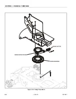
Страница 86: ...SECTION 3 CHASSIS TURNTABLE 3 44 JLG Lift 3121827 Figure 3 16 Swing Components...
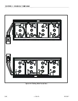
Страница 88: ...SECTION 3 CHASSIS TURNTABLE 3 46 JLG Lift 3121827 Figure 3 18 Battery Cable Connections...
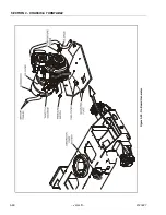
Страница 90: ...SECTION 3 CHASSIS TURNTABLE 3 48 JLG Lift 3121827 Figure 3 20 On Board Generator...
Страница 97: ...SECTION 3 CHASSIS TURNTABLE 3121827 JLG Lift 3 55 Figure 3 22 Generator Components...
Страница 100: ...SECTION 3 CHASSIS TURNTABLE 3 58 JLG Lift 3121827 Figure 3 23 Generator System Analyzer Flow Chart...
Страница 116: ...SECTION 3 CHASSIS TURNTABLE 3 74 JLG Lift 3121827 NOTES...
Страница 125: ...SECTION 4 BOOM PLATFORM 3121827 JLG Lift 4 9 Figure 4 8 Jib Platform Components and Attaching Hardware...
Страница 127: ...SECTION 4 BOOM PLATFORM 3121827 JLG Lift 4 11 Figure 4 10 Boom Limit Switches...
Страница 140: ...SECTION 4 BOOM PLATFORM 4 24 JLG Lift 3121827 Figure 4 13 Rotator Counterbalance Valve...
Страница 178: ...SECTION 5 HYDRAULICS 5 24 JLG Lift 3121827 Figure 5 26 HydraForce Cartridge Torque Value Chart...
Страница 179: ...SECTION 5 HYDRAULICS 3121827 JLG Lift 5 25 Figure 5 27 Main Valve Components Prior to S N 62642...
Страница 214: ...SECTION 6 JLG CONTROL SYSTEM 6 34 JLG Lift 3121827 NOTES...
Страница 257: ......

