SECTION 3 - CHASSIS & TURNTABLE
3-26
– JLG Lift –
3121827
7.
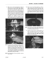
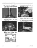
Remove commutator (5) and seal ring (3) Remove
seal ring from commutator, using an air hose to blow
air into ring groove until seal ring is lifted out and dis-
card seal ring. Inspect commutator for cracks or
burrs, wear, scoring, spalling or brinelling. If any of
these conditions exist, replace commutator and
commutator ring as a matched set.
8.
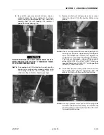
Remove manifold (7) and inspect for cracks surface
scoring, brinelling or spalling. Replace manifold if
any of these conditions exist. A polished pattern on
the ground surface from commutator or rotor rota-
tion is normal. Remove and discard the seal rings (4)
that are on both sides of the manifold.
NOTE:
The manifold is constructed of plates bonded
together to form an integral component not subject to
further disassembly for service. Compare configura-
tion of both sides of the manifold to ensure that same
surface is reassembled against the rotor set.
Содержание JLG E400AJP
Страница 2: ......
Страница 21: ...SECTION 1 SPECIFICATIONS 3121827 JLG Lift 1 7 Figure 1 2 Operator Maintenance Lubrication Diagram...
Страница 32: ...SECTION 1 SPECIFICATIONS 1 18 JLG Lift 3121827 NOTES...
Страница 42: ...SECTION 2 GENERAL 2 10 JLG Lift 3121827 NOTES...
Страница 54: ...SECTION 3 CHASSIS TURNTABLE 3 12 JLG Lift 3121827 Figure 3 3 Speed Sensor Orientation...
Страница 55: ...SECTION 3 CHASSIS TURNTABLE 3121827 JLG Lift 3 13 Figure 3 4 Frame Mounted Electrical Components Sheet 1 of 2...
Страница 56: ...SECTION 3 CHASSIS TURNTABLE 3 14 JLG Lift 3121827 Figure 3 5 Frame Mounted Electrical Components Sheet 2 of 2...
Страница 60: ...SECTION 3 CHASSIS TURNTABLE 3 18 JLG Lift 3121827 Figure 3 7 Steering Components and Spindles...
Страница 62: ...SECTION 3 CHASSIS TURNTABLE 3 20 JLG Lift 3121827 Figure 3 9 Tilt Sensor Location...
Страница 86: ...SECTION 3 CHASSIS TURNTABLE 3 44 JLG Lift 3121827 Figure 3 16 Swing Components...
Страница 88: ...SECTION 3 CHASSIS TURNTABLE 3 46 JLG Lift 3121827 Figure 3 18 Battery Cable Connections...
Страница 90: ...SECTION 3 CHASSIS TURNTABLE 3 48 JLG Lift 3121827 Figure 3 20 On Board Generator...
Страница 97: ...SECTION 3 CHASSIS TURNTABLE 3121827 JLG Lift 3 55 Figure 3 22 Generator Components...
Страница 100: ...SECTION 3 CHASSIS TURNTABLE 3 58 JLG Lift 3121827 Figure 3 23 Generator System Analyzer Flow Chart...
Страница 116: ...SECTION 3 CHASSIS TURNTABLE 3 74 JLG Lift 3121827 NOTES...
Страница 125: ...SECTION 4 BOOM PLATFORM 3121827 JLG Lift 4 9 Figure 4 8 Jib Platform Components and Attaching Hardware...
Страница 127: ...SECTION 4 BOOM PLATFORM 3121827 JLG Lift 4 11 Figure 4 10 Boom Limit Switches...
Страница 140: ...SECTION 4 BOOM PLATFORM 4 24 JLG Lift 3121827 Figure 4 13 Rotator Counterbalance Valve...
Страница 178: ...SECTION 5 HYDRAULICS 5 24 JLG Lift 3121827 Figure 5 26 HydraForce Cartridge Torque Value Chart...
Страница 179: ...SECTION 5 HYDRAULICS 3121827 JLG Lift 5 25 Figure 5 27 Main Valve Components Prior to S N 62642...
Страница 214: ...SECTION 6 JLG CONTROL SYSTEM 6 34 JLG Lift 3121827 NOTES...
Страница 257: ......


