SECTION 3 - CHASSIS & TURNTABLE
3-56
– JLG Lift –
3121827
2.
Time Delay Pre-Heat (TDPH)
TDPH, if enabled, occurs after TDES has elapsed
and the engine temperature is below the factory set
engine preheat temperature setting. The engine pre-
heater will be energized for the factory set preheat
delay period.
• RBS Startup Sequence
3.
Crank Time
The RBS will crank for a period up to the crank time
or until the engine starts.
4.
Rest Time
If the engine does not successfully start, the RBS will
wait for the rest time before attempting to crank the
engine again.
5.
Crank Cycles
The RBS will attempt to start the engine up until the
number of crank cycles is reached. If the RBS does
not start, an Over crank fault is indicated.
6.
Time Delay Bypass (TDBP)
Once the engine starts, TDBP must elapse before
low oil pressure and underspeed shutdowns are
activated. This allows the engine to come up to nor-
mal operating conditions before enabling these
shutdowns are monitored.
•
RBS Shutdown Sequence
Once all CTS conditions have been removed, the RBS will
begin the shutdown sequence. If a CTS condition is initi-
ated during the shutdown sequence, the RBS will return to
normal running operation until the CTS is removed.
1.
Time Delay Engine Run (TDER)
Once the CTS condition is removed, the TDER
period begins. This period ensures that no further
CTS conditions occur prior to the cool down period.
Time Delay Cool down (TDC)
Once the TDER period ends, the alternator output is
reduced to a minimal level in order to allow the engine to
cool down for the TDC period. If a CTS is received during
the TDC period, the CTS must last for at least the TDES
period for the RBS to return to normal running operation.
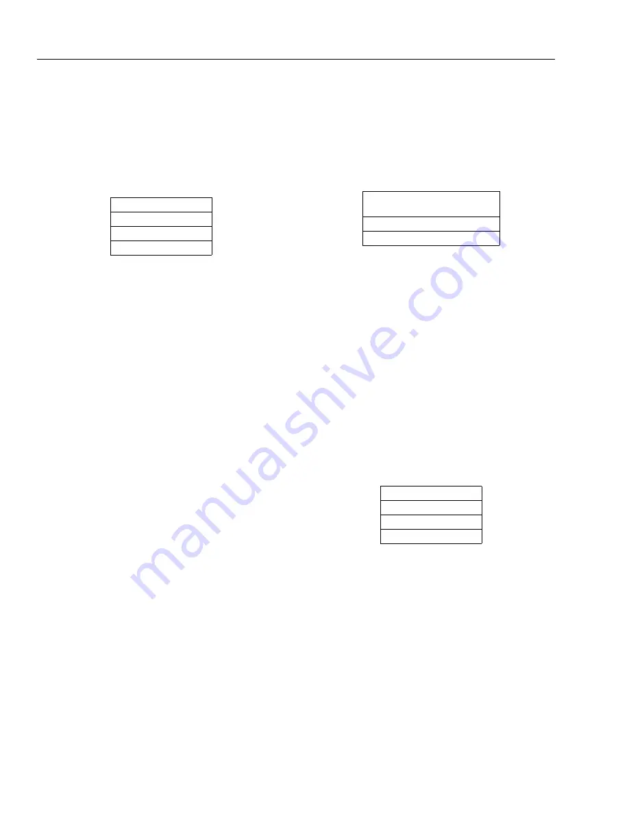
Table 3-5. RBS Prestart Sequence
CTS (Call to Start)
TDES (Engine Start)
Preheat Delay
RBS Startup Sequence
Table 3-6. RBS Startup Sequence
Crank Time -> Rest Time
(Until Engine Start or # of Crank Cycles)
TDBP Bypass
Normal Running Operation
Table 3-7. RBS Shutdown Sequence
Remove CTS
TDER Engine Run
TDC Cooldown
Engine Stop
Содержание JLG E400AJP
Страница 2: ......
Страница 21: ...SECTION 1 SPECIFICATIONS 3121827 JLG Lift 1 7 Figure 1 2 Operator Maintenance Lubrication Diagram...
Страница 32: ...SECTION 1 SPECIFICATIONS 1 18 JLG Lift 3121827 NOTES...
Страница 42: ...SECTION 2 GENERAL 2 10 JLG Lift 3121827 NOTES...
Страница 54: ...SECTION 3 CHASSIS TURNTABLE 3 12 JLG Lift 3121827 Figure 3 3 Speed Sensor Orientation...
Страница 55: ...SECTION 3 CHASSIS TURNTABLE 3121827 JLG Lift 3 13 Figure 3 4 Frame Mounted Electrical Components Sheet 1 of 2...
Страница 56: ...SECTION 3 CHASSIS TURNTABLE 3 14 JLG Lift 3121827 Figure 3 5 Frame Mounted Electrical Components Sheet 2 of 2...
Страница 60: ...SECTION 3 CHASSIS TURNTABLE 3 18 JLG Lift 3121827 Figure 3 7 Steering Components and Spindles...
Страница 62: ...SECTION 3 CHASSIS TURNTABLE 3 20 JLG Lift 3121827 Figure 3 9 Tilt Sensor Location...
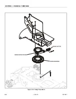
Страница 86: ...SECTION 3 CHASSIS TURNTABLE 3 44 JLG Lift 3121827 Figure 3 16 Swing Components...
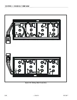
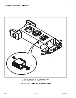
Страница 88: ...SECTION 3 CHASSIS TURNTABLE 3 46 JLG Lift 3121827 Figure 3 18 Battery Cable Connections...
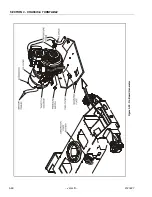
Страница 90: ...SECTION 3 CHASSIS TURNTABLE 3 48 JLG Lift 3121827 Figure 3 20 On Board Generator...
Страница 97: ...SECTION 3 CHASSIS TURNTABLE 3121827 JLG Lift 3 55 Figure 3 22 Generator Components...
Страница 100: ...SECTION 3 CHASSIS TURNTABLE 3 58 JLG Lift 3121827 Figure 3 23 Generator System Analyzer Flow Chart...
Страница 116: ...SECTION 3 CHASSIS TURNTABLE 3 74 JLG Lift 3121827 NOTES...
Страница 125: ...SECTION 4 BOOM PLATFORM 3121827 JLG Lift 4 9 Figure 4 8 Jib Platform Components and Attaching Hardware...
Страница 127: ...SECTION 4 BOOM PLATFORM 3121827 JLG Lift 4 11 Figure 4 10 Boom Limit Switches...
Страница 140: ...SECTION 4 BOOM PLATFORM 4 24 JLG Lift 3121827 Figure 4 13 Rotator Counterbalance Valve...
Страница 178: ...SECTION 5 HYDRAULICS 5 24 JLG Lift 3121827 Figure 5 26 HydraForce Cartridge Torque Value Chart...
Страница 179: ...SECTION 5 HYDRAULICS 3121827 JLG Lift 5 25 Figure 5 27 Main Valve Components Prior to S N 62642...
Страница 214: ...SECTION 6 JLG CONTROL SYSTEM 6 34 JLG Lift 3121827 NOTES...
Страница 257: ......

