SECTION 6 - JLG CONTROL SYSTEM
6-16
– JLG Lift –
3121827
6/6
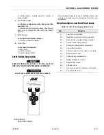
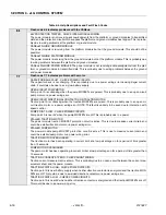
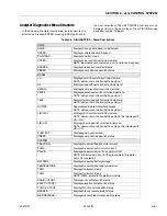
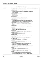
Flash code 6/6 indicates problems with the CANbus.
48V PROTECTION TRIPPED - CHECK INTER-MODULE WIRING
The power module is not receiving acknowledgments from the platform or ground modules to transmitted
data, and the protection circuit which supplies the platform and ground modules has tripped. This is proba-
bly due to wiring problems at the platform or ground module.
CANbus FAILURE: GROUND MODULE
The power module is receiving from the platform module but not the ground module. This should not be
possible!
CANbus FAILURE: PLATFORM MODULE
The power module is receiving from the ground module but not the platform module. This is probably due
to wiring problems between the platform and ground modules.
CANbus FAILURE: POWER MODULE The power module is not receiving acknowledgments from the plat-
form or ground modules to transmitted data. This is probably due to wiring problems between the ground
and power modules.
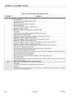
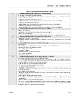
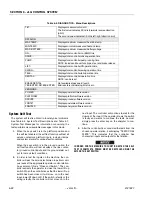
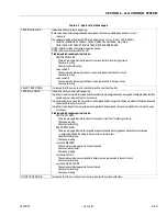
7/7
Flash code 7/7 indicates problems with a motor.
CAPACITOR BANK FAULT - CHECK POWER CIRCUITS
The capacitor bank is not charging. This is probably due to a power wiring error causing illegal current
drain; it could also be due to a very low battery supply.
OPEN-CIRCUIT PUMP MOTOR
Pump point A is collapsing when the pump MOSFETs are pulsed. This is probably due to an open circuit
pump motor or a power wiring error.
OPEN-CIRCUIT DIRECTIONAL CONTACTOR OR TRACTION MOTOR
Traction point A is collapsing when the traction MOSFETs are pulsed. This is probably due to an open cir-
cuit traction motor or a power wiring error. NOTE: This fault is unlikely to be seen due to interaction with
speed control...
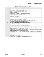
PUMP POINT A LOW - CHECK POWER CIRCUITS
Pump point A is near 0V when the pump MOSFETs are off. This is probably due to a power
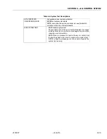
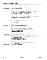
STALLED TRACTION MOTOR
The power module traction MOSFET protection circuit is active. This is due to massive current drain and
could be a stalled traction motor or a power wiring error.
STALLED PUMP MOTOR
The power module pump MOSFET protection circuit is active. This is due to massive current drain and
could be a stalled pump motor or a power wiring error.
TRACTION MOTOR OVERLOADED
The traction motor has been operating in current limit at a low percentage on for a period of time greater
than 10 seconds.
PUMP MOTOR OVERLOADED
The pump motor has been operating in current limit at a low percentage on for a period of time greater than
10 seconds.
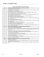
TRACTION CURRENT AT ZERO - CHECK SHUNT WIRING
Traction current measurement is at zero. This is probably due to an open-circuit between the current mea-
surement shunt and the power module.
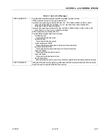
TRACTION POINT A HIGH - CHECK POWER CIRCUITS
Traction point A is near battery supply when neither direction contactor is energized and the traction MOS-
FETs are off. This could be due to a welded direction contactor or a power wiring error.
TRACTION POINT A LOW - CHECK POWER CIRCUITS
Traction point A is near 0V when neither direction contactor is energized and the traction MOSFETs are off.
This could be due to a power wiring error.
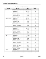
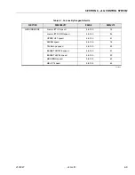
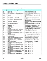
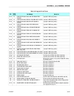
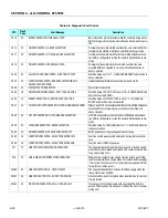
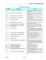
Table 6-4. Help Descriptions and Fault Flash Codes
Содержание JLG E400AJP
Страница 2: ......
Страница 21: ...SECTION 1 SPECIFICATIONS 3121827 JLG Lift 1 7 Figure 1 2 Operator Maintenance Lubrication Diagram...
Страница 32: ...SECTION 1 SPECIFICATIONS 1 18 JLG Lift 3121827 NOTES...
Страница 42: ...SECTION 2 GENERAL 2 10 JLG Lift 3121827 NOTES...
Страница 54: ...SECTION 3 CHASSIS TURNTABLE 3 12 JLG Lift 3121827 Figure 3 3 Speed Sensor Orientation...
Страница 55: ...SECTION 3 CHASSIS TURNTABLE 3121827 JLG Lift 3 13 Figure 3 4 Frame Mounted Electrical Components Sheet 1 of 2...
Страница 56: ...SECTION 3 CHASSIS TURNTABLE 3 14 JLG Lift 3121827 Figure 3 5 Frame Mounted Electrical Components Sheet 2 of 2...
Страница 60: ...SECTION 3 CHASSIS TURNTABLE 3 18 JLG Lift 3121827 Figure 3 7 Steering Components and Spindles...
Страница 62: ...SECTION 3 CHASSIS TURNTABLE 3 20 JLG Lift 3121827 Figure 3 9 Tilt Sensor Location...
Страница 86: ...SECTION 3 CHASSIS TURNTABLE 3 44 JLG Lift 3121827 Figure 3 16 Swing Components...
Страница 88: ...SECTION 3 CHASSIS TURNTABLE 3 46 JLG Lift 3121827 Figure 3 18 Battery Cable Connections...
Страница 90: ...SECTION 3 CHASSIS TURNTABLE 3 48 JLG Lift 3121827 Figure 3 20 On Board Generator...
Страница 97: ...SECTION 3 CHASSIS TURNTABLE 3121827 JLG Lift 3 55 Figure 3 22 Generator Components...
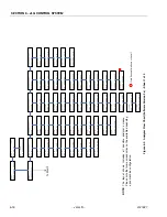
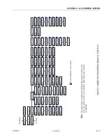
Страница 100: ...SECTION 3 CHASSIS TURNTABLE 3 58 JLG Lift 3121827 Figure 3 23 Generator System Analyzer Flow Chart...
Страница 116: ...SECTION 3 CHASSIS TURNTABLE 3 74 JLG Lift 3121827 NOTES...
Страница 125: ...SECTION 4 BOOM PLATFORM 3121827 JLG Lift 4 9 Figure 4 8 Jib Platform Components and Attaching Hardware...
Страница 127: ...SECTION 4 BOOM PLATFORM 3121827 JLG Lift 4 11 Figure 4 10 Boom Limit Switches...
Страница 140: ...SECTION 4 BOOM PLATFORM 4 24 JLG Lift 3121827 Figure 4 13 Rotator Counterbalance Valve...
Страница 178: ...SECTION 5 HYDRAULICS 5 24 JLG Lift 3121827 Figure 5 26 HydraForce Cartridge Torque Value Chart...
Страница 179: ...SECTION 5 HYDRAULICS 3121827 JLG Lift 5 25 Figure 5 27 Main Valve Components Prior to S N 62642...
Страница 214: ...SECTION 6 JLG CONTROL SYSTEM 6 34 JLG Lift 3121827 NOTES...
Страница 257: ......

