Section 4: Measure considerations
Model DMM7510 7½ Digit Graphical Sampling Multimeter Reference Manual
4-8
DMM7510-901-01 Rev. B / May 2015
Thermoelectric EMF generation
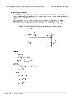
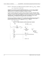
The figure below shows how thermoelectric EMFs are generated.
The test leads are made of material A, while the source under test is material B. The temperatures
between the junctions are shown as T
1
and T
2
.
Figure 138: Thermoelectric EMF generation
To calculate the thermoelectric EMFs that are generated:
E
AB
= Q
AB
(T
1
– T
2
)
where:
•
E
AB
is the generated thermoelectric EMF
•
Q
AB
is the thermoelectric coefficient of material A with respect to material B (
µ
V/°C)
•
T1 is the temperature of the B junction (°C or K)
•
T2 is the temperature of the A junction (°C or K)
A typical test setup has several copper-to-copper junctions. Each junction can have a thermoelectric
coefficient as high as 0.2
µ
V/°C. Since the two materials frequently have a several degree
temperature differential, thermoelectric EMFs of several microvolts can be generated even if
reasonable precautions are taken.
Minimizing thermoelectric EMFs
To minimize thermoelectric EMF generation:
•
Construct circuits that use the same material for all conductors. For example, connections made
by crimping copper sleeves or lugs on copper wires result in copper-to-copper junctions, which
generate minimal thermoelectric EMFs.
•
Keep connections clean and free of oxides.
•
Use low-thermoelectric cables and connections.

