Chapter 2---System Description
Model 250 Service Manual
2-5
Relay Lens Assemblies (3)
There are three Relay Lenses, one for each color. The Relay Lens focuses the
image light from the CRT onto the photosensitive layer on the input side of the
ILA
®
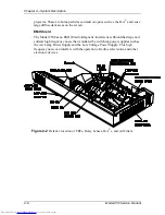
. The Relay Lens is physically connected to the CRT (see Figure 2-2).
Front Projection Lens
The Model 250 comes with a choice of four standard lenses. These include a
motorized Zoom Lens or one of three Fixed Lenses. All Projection Lenses have
motorized focus.
!
Motorized Zoom 2:1-4:1
!
Fixed Lens
"
0.96
"
1.5:1
"
5.6:1
2.4
Electronic Section
The electronics section consists of the Input Cards (VICs), the Printed Circuit
Boards (PCBs), and the CRT/Yoke assemblies.
Input Cards (VICs)
There are two standard Input Cards and four optional VICs. The Input Cards are
the first stop for the source input signal. They provide the RGB and Sync
interface for the projector. All VICs are IIC controlled.
Standard VICs:
!
Standard RGBHV VIC - The RGBHV VIC is a straight feed-through with
an IIC selection control.
!
Graphic Enhancer Plus VIC - The Graphics Enhancer Plus VIC is exactly
the same as the RGBHV VIC except for a Menu controlled adjustment for
black on white graphics and text display
Optional VICs:
!
YPbPr VIC - Composite Video Decoding for YPbPr
!
Quad Standard Decoder VIC - Composite Video Decoding (NTSC,
SECAM, and PAL)
!
Quad Standard Decoder and Line Doubler VIC - Composite Video
Decoding (NTSC, SECAM, and PAL) with Line Doubling
!
Four-Input RGBHV - Four- Input RGBHV with IIC controlled Mux
(switcher)
Содержание 250
Страница 16: ...Chapter 2 System Description Model 250 Service Manual 2 9 ...
Страница 43: ...Chapter 4 Optical 4 10 Model 250 Service Manual Figure 4 6 Optical Path ...
Страница 55: ...Chapter 5 Optical 3 4 22 Model 100 Service Manual ...
Страница 85: ...Chapter 5 Electronics 5 30 Model 250 Service Manual Figure 5 19 Convergence Deflection PCB I O Diagram ...
Страница 86: ...Chapter 5 Electronics Model 250 Service Manual 5 31 Figure 5 20 Convergence Deflection PCB I O Diagram ...
Страница 91: ...Chapter 5 Electronics 5 36 Model 250 Service Manual Figure 5 22 Scan Reversal PCB I O Diagram ...
Страница 100: ...Chapter 5 Electronics Model 250 Service Manual 5 45 Figure 5 26 Video Amplifier PCB I O Diagram ...
Страница 131: ...Chapter 5 Electronics 5 76 Model 250 Service Manual Figure 5 44 Backplane Diagram right side ...
Страница 132: ...Chapter 5 Electronics Model 250 Service Manual 5 77 ...
Страница 138: ...Chapter 6 Miscellaneous Items 6 6 Model 250 Service Manual ...
Страница 166: ...Chapter 7 Troubleshooting 7 28 Model 250 Service Manual Figure 7 19 Backplane Diagram right side ...
Страница 167: ...Chapter 7 Troubleshooting Model 250 Service Manual 7 29 ...
Страница 181: ...Chapter 8 Software and Protocol 8 14 Model 250 Service Manual ...
Страница 185: ...Chapter 9 Parts List 9 4 Model 250 Service Manual ...


